
Emulation Probe User's Manual

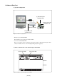
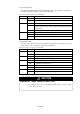
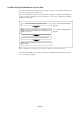
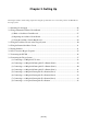

Table Of Contents
- Preface
- Contents
- 1. Precautions for Safety
- 2. Preparation
- 3. Setting Up
- 3.1 Selecting Clock Supply
- 3.2 Using an Internal Oscillator Circuit Board
- 3.3 Using the Oscillator Circuit on the Target System
- 3.4 Using the Internal Oscillator Circuit
- 3.5 Setting Switches
- 3.6 A-D Conversion Bypass Capacitor
- 3.7 Connecting the PC7501
- 3.8 Connecting the Target System
- (1) Connecting to a 100-pin LCC Socket
- (2) Connecting to a 100-pin 0.65-mm-pitch Foot Pattern (Part 1)
- (3) Connecting to a 100-pin 0.65-mm-pitch Foot Pattern (Part 2)
- (4) Connecting to a 100-pin 0.65-mm-pitch Foot Pattern (Part 3)
- (5) Connecting to a 100-pin 0.5-mm-pitch Foot Pattern (Part 1)
- (6) Connecting to a 100-pin 0.5-mm-pitch Foot Pattern (Part 2)
- (7) Connecting to a 100-pin 0.5-mm-pitch Foot Pattern (Part 3)
- (8) Connecting to a 144-pin 0.5-mm-pitch Foot Pattern
- 4. Usage
- 5. Specifications
- 6. Troubleshooting
- 7. Maintenance and Guarantee

( 26 / 76 )
Chapter 3. Setting Up
3.1 Selecting Clock Supply
There are two ways to supply a clock to the MCU, using the oscillator circuit of the emulator or using
the oscillator circuit on the target system. Table 3.1 lists the factory-settings of each clock supply.
Table 3.1 Clock supply to the MCU
IMPORTANT
Notes on Changing the Clock Supply:
• The clock supply can be set by the Init dialog box when starting up the emulator
debugger or inputting CLK command on the script window.
• For XCIN-XCOUT, it is necessary to set switches in the emulator. For details, refer to
"3.5 Setting Switches" (page 31).
Clock
DescriptionDisplay of emulator debugger
Default setting
Main
X
IN-XOUT
Sub
X
CIN
-X
COUT
Internal oscillator circuit
(OSC-3)
Oscillator of target system
Internal oscillator circuit of emulator
(32.768 kHz)
Target system
Internal
External
External
Internal
Yes
-
Yes
-
Generate
Internal generator circuit
(1.0 to 32.0 MHz)
-