To our customers, Old Company Name in Catalogs and Other Documents On April 1st, 2010, NEC Electronics Corporation merged with Renesas Technology Corporation, and Renesas Electronics Corporation took over all the business of both companies. Therefore, although the old company name remains in this document, it is a valid Renesas Electronics document. We appreciate your understanding. Renesas Electronics website: http://www.renesas.
Notice 1. 2. 3. 4. 5. 6. 7. All information included in this document is current as of the date this document is issued. Such information, however, is subject to change without any prior notice. Before purchasing or using any Renesas Electronics products listed herein, please confirm the latest product information with a Renesas Electronics sales office.
User’s Manual M30290T-EPB User’s Manual Emulation Probe for M16C/26A, 28, 29 Group MCUs Rev.1.00 2004.
* NQPACK, YQPACK, YQSOCKET, YQ-GUIDE, HQPACK, TQPACK and TQSOCKET are trademarks of Tokyo Eletech Corporation. Keep safety first in your circuit designs! z Renesas Technology Corporation and Renesas Solutions Corporation put the maximum effort into making semiconductor products better and more reliable, but there is always the possibility that trouble may occur with them. Trouble with semiconductors may lead to personal injury, fire or property damage.
Preface The M30290T-EPB is an emulation probe for the M16C/26A, 28, 29 Group MCUs. The M30290T-EPB is used by connecting to the PC7501 emulator main unit. This user's manual mainly describes specifications of the M30290T-EPB emulation probe and how to setup it. For details on the following products, which are used with the M30290T-EPB, refer to each product's user's manual. Emulator: Emulator debugger: PC7501 User's Manual M3T-PD30F User's Manual All the components of this product are shown in "Table 2.
M30290T-EPB User’s Manual Contents Chapter 1. Precautions for Safety ..................................................................................................................... 7 1.1 Safety Symbols and Meanings.................................................................................................. 8 WARNING ....................................................................................................................................... 9 Warning for Installation....................
Contents Chapter 3. Setup.............................................................................................................................................. 23 3.1 Selecting Clock Supply............................................................................................................ 24 3.1.1 Clocks............................................................................................................................ 24 3.1.2 Using an Internal Oscillator Circuit Board ..............
M30290T-EPB User’s Manual Terminology Some specific words used in this user's manual are defined as follows: PC7501 system This means an emulator system built around the PC7501 emulator. The PC7501 emulator system is configured with an emulator main unit PC7501, emulation probe M30290T-EPB, emulator debugger M3T-PD30F and host machine. Emulator main unit PC7501 This means an emulator for the M16C Family MCUs. You can configure your emulator system by changing emulation probes according to your target MCU.
Chapter 1. Precautions for Safety Chapter 1. Precautions for Safety This chapter describes precautions for using this product safely and properly. For precautions for the emulator main unit and the emulator debugger, refer to each user's manual included with your product. 1.1 Safety Symbols and Meanings................................................................................................................... 8 WARNING ................................................................................
M30290T-EPB User’s Manual 1.1 Safety Symbols and Meanings In both the user's manual and on the product itself, several icons are used to insure proper handling of this product and also to prevent injuries to you or other persons, or damage to your properties. This chapter describes the precautions which should be taken in order to use this product safely and properly. Be sure to read this chapter before using this product.
Chapter 1. Precautions for Safety WARNING Warning for Installation: z Do not set this product in water or areas of high humidity. Make sure that the main unit does not get wet. Spilling water or some other liquid into the main unit can cause an unrepairable damage. Warning for Use Environment: z This equipment is to be used in an environment with a maximum ambient temperature of 35°C. Care should be taken that this temperature is not exceeded.
M30290T-EPB User’s Manual CAUTION Caution to Be Taken for Modifying This Products: z Do not modify this product. Modifying or disassembling this product will void your warranty. Cautions to Be Taken for Turning On the Power: z Turn on the power of the emulator and user system as simultaneously as possible. And also, turn off the power of the emulator and user system as simultaneously as possible.
Chapter 1. Precautions for Safety IMPORTANT Notes on Downloading Firmware: z Before using this product for the first time, it is necessary to download the dedicated firmware. Please note that, to do this, it is necessary to start up the emulator main unit in maintenance mode. For downloading firmware, see "4.2 Downloading Firmware" (page 40). Once the firmware has been downloaded, the product can be used by simply turning on the power. z Do not shut off the power while downloading the firmware.
M30290T-EPB User’s Manual IMPORTANT Notes on Maskable Interrupts: z Even if a user program is not being executed (including when run-time debugging is being performed), the evaluation MCU keeps running so as to control the emulation probe. Therefore, timers and other components do not stop running.
Chapter 1. Precautions for Safety IMPORTANT Note on Accessing Addresses 00000h and 00001h: z With the M16C/Tiny Series MCUs, when a maskable interrupt is generated, the interrupt data (interrupt number and interrupt request level) stored in addresses 00000h and 00001h are read out. Also, the interrupt request bit is cleared when address 00000h or 00001h is read out.
M30290T-EPB User’s Manual IMPORTANT Notes on Address-Match Interrupts: z When you use the address-match interrupt function in a user program, uncheck "Enable the Address Match Interrupt Break Function" in the MCU tab of the Init dialog box of the emulator debugger. Thus, normal software breaks are used for the internal RAM and ROM areas of an MCU. z Do not set a software break at an address where an address-match interrupt occurs. Otherwise, a user program may be run out of control.
Chapter 1. Precautions for Safety IMPORTANT Note on DMA Transfer: z With this product, the program is stopped with a loop program to a specific address. Therefore, if a DMA request is generated while the program is stopped, DMA transfer is executed. However, make note that DMA transfer while the program is stopped may not be performed correctly. Also note that the below registers have been changed to generate DMA transfer as explained here even when the program is stopped.
M30290T-EPB User’s Manual IMPORTANT Notes on Debugging in CPU Rewrite Mode: z When you debug M16C/26A, 28, 29 Group MCUs in CPU rewrite mode, do not change the block 0 area (FF000h--FFFFFh) of the flash ROM. Otherwise, the emulator will be uncontrollable. z If you check "Debug the program using CPU Rewrite Mode" in the MCU tab of the Init dialog box of the emulator debugger, you cannot use the following functions.
Chapter 2. Preparation Chapter 2. Preparation This chapter describes the package components, the system configuration and the preparation for using this product for the first time. 2.1 Package Components .............................................................................................................................. 18 2.2 Other Tool Products Required for Development ...................................................................................... 18 2.3 Name of Each Part ...............
M30290T-EPB User’s Manual 2.1 Package Components The M30290T-EPB package consists of the following items. When unpacking it, check to see if your M30290T-EPB contains all of these items. Table 2.
Chapter 2. Preparation 2.3 Name of Each Part 2.3.1 System Configuration Figure 2.1 shows a configuration of the PC7501 system. Host machine interface (LPT parallel, USB or LAN) Host machine Emulator main unit PC7501 (1) Emulation probe M30290T-EPB (2) Converter board M30290T-80FPD etc. User system Figure 2.
M30290T-EPB User’s Manual 2.3.2 Names and Functions of the PC7501 Upper Panel LEDs Figure 2.2 shows the names of the LEDs on the upper panel of the PC7501. System status LED Target status LED Figure 2.2 Names of the LEDs on the upper panel of the PC7501 (1) System Status LEDs The system status LEDs indicate the emulator PC7501's power supply, firmware operating status, etc. Table 2.3 lists the definition of each system status LED. Table 2.
Chapter 2. Preparation (2) Target Status LEDs The target status LEDs indicate operating status of the target MCU and power supply of the user system. Table 2.4 lists the definition of each target status LED. Table 2.4 Definition of the target status LEDs Name POWER CLOCK RESET RUN WARNING Status ON OFF ON OFF ON OFF ON OFF ON OFF Meaning Power is supplied to the user system. Power is not supplied to the user system. Target MCU clock is oscillating. Target MCU clock is not oscillating.
M30290T-EPB User’s Manual 2.4 When Using the Emulator for the First Time 2.4.1 Downloading Firmware If you have purchased this emulation probe newly, you need to download the firmware. The download procedure is given in Figure 2.3. Before downloading the firmware, check that emulator debugger M3T-PD30F is installed to your host machine and the PC7501 is connected to the host machine. For more details, see each user's manual of the emulator debugger M3T-PD30F and the PC7501.
Chapter 3. Setup Chapter 3. Setup This chapter describes switch settings required for using this product and how to connect this product to the PC7501 and the user system. 3.1 Selecting Clock Supply............................................................................................................................. 24 3.1.1 Clocks.............................................................................................................................................. 24 3.1.
M30290T-EPB User’s Manual 3.1 Selecting Clock Supply 3.1.1 Clocks You can choose a clock supplied to the evaluation MCU by the Emulator tab in the Init dialog box of the emulator debugger. Table 3.1 shows the clocks and their initial settings. Table 3.
Chapter 3. Setup 2. Replace the oscillator circuit board (see Figure 3.2). The oscillator circuit board of the PC7501 is in the lower right corner of the board. Unscrew the screw securing the oscillator circuit board. Lift off the oscillator circuit board. Attach another oscillator circuit board to the connector. Secure the new oscillator circuit board with the screw. Figure 3.2 Replacing the oscillator circuit board 3. Reinstall the upper cover and secure the four screws.
M30290T-EPB User’s Manual (3) Using the Internal Oscillator Circuit Bare Board To use the emulation probe at a frequency you like, build a desired oscillator circuit on the included OSC-2 oscillator circuit bare board. Figure 3.3 shows an external view of the OSC-2 oscillator circuit bare board and where the connector pins are located. Figure 3.4 shows the circuitry of the oscillator circuit bare board OSC-2. Use the number of oscillator circuits recommended by the oscillator manufacturer.
Chapter 3. Setup 3.1.3 Using the Oscillator Circuit on the User System To operate this product with an external clock, construct the oscillator circuit as shown in Figure 3.5 in the user system and input the oscillator output at 50% duty (within the operating range of the evaluation MCU) into pin XIN. And pin XOUT should be open. Choose "External" in the emulator debugger to use this clock. Figure 3.5 External oscillator circuit Make note that in the oscillator circuit shown in Figure 3.
M30290T-EPB User’s Manual 3.1.4 Using the Internal Generator Circuit The dedicated circuit in the PC7501 can generate any arbitrary frequency specified by the emulator debugger, and it can be supplied as a main clock. It does not depend on either the oscillator circuit board in the PC7501 or the oscillator circuit on the user system. If you want to debug programs without the user system or change a frequency temporarily, you can check its operation before purchasing an oscillator.
Chapter 3. Setup 3.2 A-D Conversion Bypass Capacitors There is a foot pattern on the M30290T-EPBM board for mounting bypass capacitors for the A-D conversion circuit near the MCU. Mount suitable bypass capacitors as occasion demands. Figure 3.7 shows where they are installed and the configuration of this product. Back side of the M30290T-EPBM AVCC-AVSS bypass capacitor AVSS AVCC C1 VREF-AVSS bypass capacitor AVSS VREF C2 Figure 3.
M30290T-EPB User’s Manual 3.3 Connecting the PC7501 Figure 3.8 shows how to connect the PC7501 and the emulation probe. M3T-FLX160-EPB Emulation probe Figure 3.8 Connecting the PC7501 and the emulation probe CAUTION Notes on Connecting the PC7501: z When connecting the emulation probe, be sure to hold the both sides of the emulation probe horizontally and insert it directly. z Always shut OFF power before connecting the emulation probe. Otherwise, internal circuits may be damaged.
Chapter 3. Setup 3.4 Connecting the User System Figure 3.9 shows how to connect this product according to your user system. Emulation probe M30290T-EPB 42-pin 0.8-mm-pitch M30263T-42SSB SSOP Socket frame (x2) *1 M3T-SSOP42B-450 *1 48-pin 0.5-mm-pitch LQFP M30260T-48FPD 64-pin 0.5-mm-pitch M30291T-64FPD LQFP YQ-GUIDE (x4) *2 YQ-GUIDE (x4) *3 YQPACK048SD *2 YQPACK064SD *3 NQPACK048SD *2 NQPACK064SD-ND *3 80-pin 0.
M30290T-EPB User’s Manual 3.4.1 Connecting to a 42-pin 0.8-mm-pitch Foot Pattern Here following is a procedure of connecting to a 42-pin 0.8-mm-pitch foot pattern on the user system using the M30263T-42SSB (included with the M30263T-EPB-FP). For details on the M30263T-42SSB, refer to its user's manual. (1) (2) (3) (4) Mount the socket main unit included with the M30263T-42SSB to the user system. Attach the M3T-SSOP42B-450 included with the M30263T-42SSB and the socket frame to the socket main unit.
Chapter 3. Setup 3.4.2 Connecting to a 48-pin 0.5-mm-pitch Foot Pattern Here following is a procedure of connecting to a 48-pin 0.5-mm-pitch foot pattern on the user system using the M30260T-48FPD (included with the M30260T-EPB-GP). For details on the M30260T-48FPD, refer to its user's manual. (1) Mount the NQPACK048SD included with the M30260T-48FPD to the user system. (2) Attach the YQPACK048SD included with the M30260T-48FPD to the NQPACK048SD and secure it with the YQ-GUIDE's.
M30290T-EPB User’s Manual 3.4.3 Connecting to a 64-pin 0.5-mm-pitch Foot Pattern Here following is a procedure of connecting to a 64-pin 0.5-mm-pitch foot pattern on the user system using the M30291T-64FPD (included with the M30291T-EPB-HP). For details on the M30291T-64FPD, refer to its user's manual. (1) Mount the NQPACK064SD-ND included with the M30291T-64FPD to the user system. (2) Attach the YQPACK064SD included with the M30291T-64FPD to the NQPACK064SD-ND and secure it with the YQ-GUIDE's.
Chapter 3. Setup 3.4.4 Connecting to an 80-pin 0.5-mm-pitch Foot Pattern Here following is a procedure of connecting to an 80-pin 0.5-mm-pitch foot pattern on the user system using the M30290T-80FPD (included with the M30290T-EPB-HP). For details on the M30290T-80FPD, refer to its user's manual. (1) Mount the NQPACK080SD-ND included with the M30290T-80FPD to the user system. (2) Attach the YQPACK080SD included with the M30290T-80FPD to the NQPACK080SD-ND and secure it with the YQ-GUIDE's.
M30290T-EPB User’s Manual MEMO ( 36 / 58 )
Chapter 4. Usage Chapter 4. Usage This chapter describes from turning on the power of this product to starting up the emulator debugger. 4.1 Turning On the Power .............................................................................................................................. 38 4.1.1 Checking Connections of the Emulator System.............................................................................. 38 4.1.2 Turning ON/OFF the Power ........................................................
M30290T-EPB User’s Manual 4.1 Turning On the Power 4.1.1 Checking Connections of the Emulator System Before turning the power ON, check the connection of the interface cable to the host machine, PC7501, emulation probe, and user system. 4.1.2 Turning ON/OFF the Power z Turn ON the power of the emulator and user system as simultaneously as possible. Turn OFF the power of the emulator and user system as simultaneously as possible.
Chapter 4. Usage 4.1.4 LED Display When the PC7501 Starts Up Normally Figure 4.1 shows upper panel LED lighting status when the emulator started up properly. Check it when starting up the emulator system. ・If this LED does not light, check the voltage of the user system. ・Check that power is supplied to all the power terminals. ・When the user system is not connected, this LED does not light. POWER SAFE ERROR POWER CLOCK RESET RUN WARNING SYSTEM TARGET STATUS STATUS : ON : OFF : Flashing Figure 4.
M30290T-EPB User’s Manual 4.2 Downloading Firmware 4.2.1 When It is Necessary to Download Firmware It is necessary to download the firmware in the cases listed below. Normally, the following are automatically detected when the emulator debugger is started up, and the firmware is downloaded.
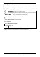
Chapter 4. Usage 4.3 Self-check 4.3.1 Self-check Procedure To run the self-check of the emulator, do so as explained here below. While the self-check is in progress, the LEDs will change as shown in Figure 4.3. (1) If the user system is connected, disconnect it. (2) Within 2 seconds of activating power to the emulator, press the system reset switch on the emulator front panel to switch the emulator to maintenance mode. (3) Check the SAFE LED starts flashing and then press the system reset switch again.
M30290T-EPB User’s Manual 4.3.2 If an Error is Detected in the Self-check If the self-check does not result normally (ERROR 1 to ERROR 4 in Figure 4.3), check the following. z Whether the emulation probe and PC7501 are connected properly. z Whether the proper firmware has been downloaded. IMPORTANT Note on Self-check: z If the self-check do not result normally (excluding user system errors), the emulation probe may be damaged. Then contact your local distributor.
Chapter 5. Specifications Chapter 5. Specifications This chapter describes specifications of this product. 5.1 Specifications ........................................................................................................................................... 44 5.2 Connection Diagram................................................................................................................................. 45 5.3 External Dimensions...............................................................
M30290T-EPB User’s Manual 5.1 Specifications Table 5.1 lists the specifications of the M30290T-EPB. Table 5.
Chapter 5. Specifications 5.2 Connection Diagram Figures 5.1 shows a connection diagram of the M30290T-EPB. This connection diagram mainly shows the interface section. The circuits not connected to the user system such as the emulator's control system are omitted. The signals not shown in Figure 5.1 connect the evaluation MCU and the user system directly. Table 5.2 shows IC electric characteristics of this product for reference purposes.
M30290T-EPB User’s Manual 5.3 External Dimensions 5.3.1 External Dimensions of the Emulation Probe Figure 5.2 shows external dimensions of the M30290T-EPB connected with the M30290T-PTCB. 11.0 26.3 60.0 85.0 Unit: mm Figure 5.
Chapter 5. Specifications 5.3.2 External Dimensions of the Converter Board M30263T-42SSB Figure 5.3 shows external dimensions and a sample foot pattern of the converter board M30263T-42SSB (included with the M30263T-EPB-FP) for a 42-pin 0.8-mm-pitch SSOP. 16.00 ±0.1 6.5 Max9.0 32.0 Min14.5 35.0 0 0.40 +0.1 0.80 ±0.05 0.28 0.20 ±0.05 0.80 ±0.05 Unit: mm Figure 5.3 External dimensions and a sample foot pattern of the converter board M30263T-42SSB 5.3.
M30290T-EPB User’s Manual 5.3.4 External Dimensions of the Converter Board M30291T-64FPD Figure 5.5 shows external dimensions and a sample foot pattern of the converter board M30291T-64FPD (included with the M30291T-EPB-HP) for a 64-pin 0.5-mm-pitch LQFP. 36.0 14.0 10.0 32.0 0.25 16.5 0.5 10.0 14.0 Unit: mm Figure 5.5 External dimensions and a sample foot pattern of the converter board M30291T-64FPD 5.3.5 External Dimensions of the Converter Board M30290T-80FPD Figure 5.
Chapter 6. Troubleshooting Chapter 6. Troubleshooting This chapter describes how to troubleshoot when this product does not work properly. 6.1 Flowchart to Remedy the Troubles .......................................................................................................... 50 6.2 When the Emulator Debugger Does Not Start Up Properly.....................................................................
M30290T-EPB User’s Manual 6.1 Flowchart to Remedy the Troubles Figure 6.1 shows the flowchart to remedy the troubles from when power to the emulator is activated until the emulator debugger starts up. Check this while the user system is disconnected. For the latest FAQs visit the Renesas Tool Homepage. http://www.renesas.
Chapter 6. Troubleshooting 6.2 When the Emulator Debugger Does Not Start Up Properly (1) When the LEDs of the PC7501 Shows an Error Table 6.1 Errors LEDs show and their checkpoints LEDs do not light up. Connection to the user system - All LEDs remain lit. - Error TARGET STATUS POWER LED does not light up. TARGET STATUS CLOCK LED does not light up. Connected Not connected Connected TARGET STATUS RESET LED does not go out. Connected Checkpoint Check that the power cable is connected to the PC7501.
M30290T-EPB User’s Manual (2) MCU Setting Dialog Box Does Not Appear at Debugger Startup Table 6.2 Checkpoints of errors at debugger startup Error Communication error occurred. Data was not sent to the target. Checkpoint Check that all emulator debugger settings, interface cable settings and switches on the rear of the PC7501 match. See the user's manuals of the PC7501 and emulator debugger. User system cannot be properly built. (1) Download the proper firmware. See "4.2 Downloading Firmware" (page 40).
Chapter 7. Maintenance and Guarantee Chapter 7. Maintenance and Guarantee This chapter describes how to maintenance, repair provisions and how to request for repair. 7.1 7.2 7.3 7.4 Maintenance ............................................................................................................................................. 54 Guarantee.................................................................................................................................................
M30290T-EPB User’s Manual 7.1 Maintenance If dust or dirt collects on any equipment of your emulation system, wipe it off with a dry soft cloth. Do not use thinner or other solvents because these chemicals can cause the equipment's surface coating to separate. 7.
Chapter 7. Maintenance and Guarantee 7.4 How to Make Request for Repair If your product is found faulty, follow the procedure below to send your product for repair. Customer Fill in the Repair Request Sheet included with this product, then send it along with this product for repair to your local distributor. Make sure that information in the Repair Request Sheet is written in as much detail as possible to facilitate repair.
M30290T-EPB User’s Manual MEMO ( 56 / 58 )
M30290T-EPB User’s Manual Rev.1.
M30290T-EPB User’s Manual 1753, Shimonumabe, Nakahara-ku, Kawasaki-shi, Kanagawa 211-8668 Japan REJ10J0388-0100Z