M37641T2-RPD-E Emulation Pod for 7641 and 7643 Group MCUs User's Manual Rev.1.
* IC61-080-081 is a product of Yamaichi Electronics Co., Ltd. Keep safety first in your circuit designs! • Renesas Technology Corporation and Renesas Solutions Corporation put the maximum effort into making semiconductor products better and more reliable, but there is always the possibility that trouble may occur with them. Trouble with semiconductors may lead to personal injury, fire or property damage.
Preface The M37641T2-RPD-E is an emulation pod for the 7641 and 7643 Groups of Renesas 16-bit microcomputers. It's used with a PC4701 emulator. This user's manual mainly describes specifications of the M37641T2-RPD-E emulation pod and how to setup it. For details on the following products, which are used with the M37641T2-RPD-E, refer to each product's user's manual. • Emulator: PC4701 User's Manual • Emulator debugger: M3T-PD38 User's Manual All the components of this product are shown in "2.
Contents Chapter 1. Precautions for Safety ........................................................................................... 7 1.1 Safety Symbols and Meanings .............................................................................. 8 Chapter 2. Preparation .......................................................................................................... 17 2.1 Terminology ........................................................................................................ 18 2.
4.4 Self-check ............................................................................................................ 42 (1) Self-check Procedure ............................................................................... 42 (2) If an Error is Detected in the Self-check .................................................. 42 Chapter 5. Specifications ...................................................................................................... 45 5.1 Specifications ..........................
MEMO ( 6 / 68 )
Chapter 1. Precautions for Safety This chapter describes precautions for using this product safely and properly. For precautions for the emulator main unit and the emulator debugger, refer to each user's manual included with your product. 1.1 Safety Symbols and Meanings ..................................................................................................... 8 WARNING Warning for Installation ...............................................................................................
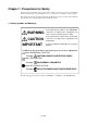
Chapter 1. Precautions for Safety In both the user's manual and on the product itself, several icons are used to insure proper handling of this product and also to prevent injuries to you or other persons, or damage to your properties. This chapter describes the precautions which should be taken in order to use this product safely and properly. Be sure to read this chapter before using this product. 1.
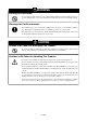
WARNING Warning for Installation: • Do not set this product in water or areas of high humidity. Make sure that the main unit does not get wet. Spilling water or some other liquid into the main unit can cause an unrepairable damage. Warnings for Use Environment: • The emulation pod is air-cooled with the ventilation slot. Therefore, do not block the ventilation slot. When heated to high temperatures, the emulation pod may not work properly.
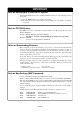
IMPORTANT Note on Malfunctions in the PC4701 System: • If the emulator malfunctions because of interference like external noise, do the following to remedy the trouble. (1) Press the RESET button on the emulator front panel. (2) If normal operation is not restored after step (1), shut OFF power to the emulator once and then reactivate it. Note for PC4700 System: • PC4700H products whose serial number ends with a number or D, DE, G cannot be used with the M37641T2-RPD-E.
IMPORTANT Notes on the Target System: • As pin Vcc of emulator is connected to the target system to observe the voltage of the target system, the target system is not powered by the emulator. Therefore design your system so that the target system is powered separately. • The voltage of the target system should be within the range of the MCU specification and +3.0 to +3.6 V or +4.5 to 5.25 V. • Do not change the voltage of the target system after turning on the power.
IMPORTANT Note on Differences between the Actual MCU and Emulator: • Emulator operation differs from mask MCU operation as listed below. (1) Reset condition (2) Power voltage When using the emulator, it is not possible to use with the range of 4.15 to 4.5 V. (3) Initial values of internal resources data at power-on (3) Internal memory (ROM and RAM) capacities, etc.
IMPORTANT Notes on the Watchdog Function: • The MCU's watchdog timer can be used only while a program is being executed. To use it otherwise, disable the watchdog timer. • If the reset circuit of the target system has a watchdog timer, disable it when using the emulator. Note on DMA Transfer: • When using the DMA transfer function, pay attention to the following. (1) Breaks are not executed during the DMA transfer. Break are executed after the DMA transfer is finished.
IMPORTANT Note on Reading MCU Internal Resources: • When the M37641T2-RPD-E is configured with the emulator debugger, the following results occur when reading MCU internal resources (SFR and internal RAM area). In both cases, data is not displayed correctly, but internal data is not affected at all. (1) Real-time tracing Data values in the MCU internal resource read cycle are not displayed correctly.
IMPORTANT Note on Stack Area: • With this product, a maximum 3 bytes of the user stack is consumed as work area. Note on Quitting the Emulator Debugger: • To restart the emulator debugger, always shut power to the emulator module off once and then on again. Notes on Connecting the Target System: • When connecting the FLX100 flexible board and the converter board, be careful not to forcibly press the connector top of the converter board.
MEMO ( 16 / 68 )
Chapter 2. Preparation This chapter describes the package components, the system configuration and the preparation for using this product for the first time. 2.1 Terminology ............................................................................................................................... 18 2.2 Package Components.................................................................................................................. 19 2.3 Other Tool Products Required for Development.................
Chapter 2. Preparation 2.1 Terminology Some specific words used in this user's manual are defined as follows: Emulator system This means an emulator system built around the PC4701 emulator. The PC4701 emulator system is configured with an emulator main unit, emulation pod, host machine and emulator debugger. Emulator main unit (Hereafter PC4701) This means a generic name for emulators for 8 and 16-bit MCUs. For details on specific models of PC4701, visit the Renesas Tools Homepage at: http://www.renesas.
2.2 Package Components The M37641T2-RPD-E package consists of the following items. When unpacking, check to see if your M37641T2-RPD-E package contains all the items listed below. Package components Item Quantity Emulation pod main unit M37641T2-RPD-E 1 Flexible cable FLX120-RPD for connecting PC4701 1 Converter board M3T-FLX-80LCC for 80-pin LCC package 1 IC socket IC61-080-081 (80-pin 0.8-mm-pitch) made by Yamaichi Electronics Co., Ltd.
2.4 Name of Each Part (1) System Configuration Figure 2.1 System configuration (1) to (4) in Figure 2.1 are included with this product package. (1) Emulation pod M37641T2-RPD-E This emulation pod contains an evaluation MCU, emulation memory and circuit to feature the debugging functions. (2) Flexible cable FLX120-RPD This 120-pin flexible cable connects the PC4701 emulator and the emulation pod. (3) Flexible cable FLX100 This 100-pin flexible cable connects the emulation pod and the target system.
(2) Inside of the Emulation Pod Figure 2.2 Internal view of the emulation pod (1) Base board Base board for the 740 Family MCUs which controls the interface with the PC4701 and the evaluation MCU. (2) Memory board Board on which the 128 KB emulation memory is mounted. (3) Oscillator circuit board Board on which the oscillator circuit in the emulation pod is mounted. Its operating frequency can be changed by replacing this board with other available oscillator circuit boards.
2.5 Using the Emulator for the First Time If you have purchased this emulation pod newly, it is necessary to download firmware. The download procedure is given in Figure 2.3. Before attempting to download firmware, check the emulator debugger is installed and the emulator is connected to the host machine. For more information, see each user's manual of the emulator debugger and the PC4701. Connect the PC4701 and this product. See "3.6 Connecting the PC4701 and Emulation Pod" (page 34).
Chapter 3. Setting Up This chapter describes switch settings required for using this product and how to connect this product to the PC4701 and the target system. 3.1 Removing the Upper Cover ........................................................................................................ 24 3.2 Replacing the Evaluation MCU.................................................................................................. 25 3.3 Switch Settings .........................................................
Chapter 3. Setting Up To use this emulation pod with your application system, it is necessary to set as follows. Set the following after removing the upper cover. • Pins XIN and XOUT • Pins XCIN and XCOUT • USB-related pins (Pins Ext. Cap, D+ and D-) • Input frequency • Evaluation MCU 3.1 Removing the Upper Cover The procedure of removing the upper cover is shown below. (1) Remove the four screws of both sides of this product and lift off the upper cover (see Figure 3.1). (2) Set the jumper switches etc.
3.2 Replacing the Evaluation MCU It is necessary to replace the evaluation MCU according to the MCU you use. [MCU Group] [Evaluation MCU] 7641 Group: 7643 Group: M37641M8-XXXFS M37643M8-XXXFS To debug the 7643 Group, it is necessary to replace the evaluation MCU to the included M37643M8XXXFS. When replacing the evaluation MCU, align the No. 1 pin as shown in the Figure 3.2. Especially be careful not to insert the MCU in a wrong direction. Otherwise, it may cause a fatal damage to the MCU.
3.3 Switch Settings Figure 3.3 shows the positions of the switches and Table 3.1 shows each switch setting. Figure 3.3 Positions of the switches and their factory-settings * Switches SW3 to SW6 have not been mounted. These switches cannot be used. * For the circuit configuration of the switches, refer to "5.2 Connection Diagrams" (page 47).
Table 3.1 Switch settings of the M37641T2-RPD-E Switch setting P50 SW1 XCIN (Factory-setting) NC Description P50 side [Using as a port] When using pin P50/XCIN as a port, set to this side. [Using as a sub-clock] When using P50/XCIN as a subclock and selecting the XCIN oscillator circuit on the target board, set to this side. XCIN side [Using as a sub-clock] When using pin P50/XCIN as a sub-clock and selecting the XCIN oscillator circuit OSC-2 in the emulation pod, set to XCIN side.
3.4 Connecting USB-related Signals This section explains emulation pod specifications for each USB-related pin. (1) Pins D+ and DIn the factory-setting, electrical characteristics differ from those of the actual MCU because of the flexible cable between the emulation MCU and target system. If there are problems with electrical characteristics because of the flexible cable, the USB connector on the emulation pod can be used.
(2) Pin Ext. Cap In the factory-setting, the emulation pod processes the pin and does not connect it to the target system. • When the emulation pod processes the pin (factory-setting) Set SW8 of the emulation pod to INT side. The connection in the emulation pod is shown in Figure 3.6 below. Figure 3.6 Connecting pin Ext. Cap (SW8 = INT) • When Connecting to the target system Set SW8 of the emulation pod to EXT side. The connection to the target system is shown in Figures 3.7 and 3.8 below.
(3) Pins LPF, AVss and AVcc These pins are processed in the emulation pod, and not connected to the target system. The connection in the emulation pod is shown in Figure 3.9 below. Figure 3.9 Connecting pins LPF, AVss and AVcc IMPORTANT Note on Connecting USB-related Pins: • Pins LPF, AVss and AVcc are not connected to the target system. 3.
(1) Using the Oscillator Circuit on the Target System When you turn on the power supply, the internal clock of the emulation pod is selected to supply the clock to the MCU. To use the external clock on the target system, change the clock by the CLK command of the emulator debugger. (For details, refer to the user's manual of the emulator debugger.) IMPORTANT Notes on the External Clock: • Make note that in the oscillator circuit shown in Figure 3.
(2) Changing the Oscillator Circuit in the Emulation Pod Oscillator circuit boards for 24 MHz (for XIN) and 32.768 kHz (for XCIN) are mounted in this product. To use the emulation pod at a frequency other than 24 MHz or 32.768 kHz, build the desired oscillator circuit on the included oscillator circuit board OSC-2 (bare board) and replace the board installed in the emulation pod when shipped from the factory. Figure 3.
(3) Replacing the Oscillator Circuit Boards Figure 3.14 shows how to replace the oscillator circuit boards. For the position of the oscillator circuit board, see "Figure 2.2 Internal view of the emulation pod" (page 21). (1) Unscrew the screw connecting the oscillator circuit board. (2) Lift off the oscillator circuit board. (3) Attach the J1 connector of another oscillator circuit board for replacement to the connectors J5 (XCIN) or J6 (XIN) of the MCU-dependent board M37641TRPDM.
3.6 Connecting the PC4701 and Emulation Pod To connect the emulation pod to the PC4701, use 120-pin flexible cable FLX120-RPD included with this product package. Connect the PC4701 side connector of the FLX120-RPD to the cable connector of the PC4701, then secure with the two screws. (1) Connecting the Cable to the PC4701 Figure 3.15 shows how to connect the PC4701 and FLX120-RPD. Figure 3.
(2) Connecting the Cable to the Emulation Pod Figure 3.16 shows how to connect the FLX120-RPD and the emulation pod. Figure 3.16 Connecting the emulation pod and FLX120-RPD CAUTION Note on Connecting the Cable: • Always shut OFF power before connecting the cable. Otherwise internal circuits can be destroyed. Note on Securing the Screws: • After connecting the emulation pod to the cable, be sure to secure the screws.
3.7 Connecting the Target System You can connect the emulation pod to the target system as shown in Figure 3.17 below. Figure 3.14 Connecting the emulation pod and target system *1 These three items are available in one package. *2 The M3T-FLX-80LCC and IC61-080-081 are included in this emulation pod package. * To purchase the M3T-FLX100-T, M3T-FLX100-R, M3T-80LCC-QSD, M3T-DUMMY80, M3T-FLX-80NRA and M3T-FLX-80NSD, contact your local distributor. * The IC61-080-081 is a product of Yamaichi Electronics Co.
Chapter 4. Usage This chapter describes from turning on the power of this product to starting up the emulator debugger. 4.1 Turning On the Power ................................................................................................................ 38 (1) Checking the Connections of the Emulator System ............................................................. 38 (2) Turning On the Power...........................................................................................................
Chapter 4. Usage 4.1 Turning On the Power (1) Checking the Connections of the Emulator System Before turning the power ON, check the connection of the PC4701, emulation pod, converter board and target system. (2) Turning On the Power Power ON/OFF the target system and PC4701 as simultaneously as possible. CAUTION Notes on Power Supply: • The emulator's pin VCC is connected to the target system in order to monitor target system voltage.
(3) LED Display When the PC4701 Starts Up Normally After the emulator starts up, check the status of the LEDs on the front panel to see whether emulation pod operation is enabled or not. Figure 4.1 shows the front panel LED lighting status when the emulator is turned ON. When using M3T-PD38 V.3.00 Release 1 or greater When turning ON the power When starting up M3T-PD38 When the target system is connected, this LED lights. When it is not lighting, check the power voltage of the target system.
4.2 Downloading Firmware (1) When It is Necessary to Download Firmware It is necessary to download firmware when: (1) you use this product for the first time. (2) firmware has been upgraded. (3) the emulator debugger has been upgraded. (4) you use this product with the PC4701 which was used with another emulation pod before. (2) Downloading Firmware in Maintenance Mode Download firmware in maintenance mode as explained here following. Do NOT connect the target system when downloading firmware.
4.3 Starting Up Emulator Debugger (Init Dialog Box Settings) The Init dialog box shown in Figure 4.3 will appear after starting up the emulator debugger. Here explains the settings in the MCU tab and Clock tab in the Init dialog box. The dialog box shown below is an example of the emulator debugger M3T-PD38 V.5.10 Release 2. For more details, refer to the M3T-PD38 User's Manual. Figure 4.3 INIT dialog box (1) Settings in the CLOCK Tab MCU file: To debug 7641/7643 Group MCUs, choose the "M37640.mcu" file.
(2) Settings in the MCU Tab Make the settings of the clock supply. Main Choose an clock supply for pin XIN. INTERNAL: S u p p l i e d f r o m t h e oscillator circuit board of the emulation pod EXTERNAL: S u p p l i e d f r o m a n oscillator circuit of the target system 4.4 Self-check (1) Self-check Procedure To use the self-check function of the PC4701, do so as explained here below. While the self-check is in progress, LEDs will change as shown in Figure 4.4.
Figure 4.
MEMO ( 44 / 68 )
Chapter 5. Specifications This chapter describes specifications of this product. 5.1 Specifications ............................................................................................................................. 46 5.2 Connection Diagrams ................................................................................................................. 47 5.3 Operation Timing .......................................................................................................................
Chapter 5. Specifications 5.1 Specifications Table 5.1 lists the specifications of the M37641T2-RPD-E. Table 5.1 Specifications of the M37641T2-RPD-E Emulator PC4701 Applicable MCU 7641 Group M37641M8, M37641F8 7643 Group M37643M8, M37643F8 Evaluation MCU 7641 Group M37641M8-XXXFS (premounted) 7643 Group M37643M8-XXXFS (included) Usable modes • Single-chip mode • Memory expansion mode • Microprocessor mode Emulation memory Changeable 128 KB Maximum operating frequency VCC = 3.0 to 3.
5.2 Connection Diagrams Figures 5.1 and 5.2 show the connection diagrams of the M37641T2-RPD-E. These connection diagrams mainly show the interface section, and the circuits which are not connected to the target system such as the emulator's control system are omitted. *: Signal processed in emulator • Switches SW2, SW4, SW5 and SW6 are not mounted. • Test pin TP1 is mounted to Pin 1 of the USB connector (J7).
Figure 5.
5.3 Operation Timing With this emulator system, ports P0 to P3 and P40 are connected via the emulation circuit. Therefore, I/O timing will differ from that of the actual MCU. Use the following as a reference when using the emulation pod. (1) Operation Timing When Using the Evaluation MCU (M37641M8-XXXFS) Table 5.2 Timing requirements and switching characteristics (Vcc = 5.0V, Ø = 12 MHz) Standard value Symbol Item Actual MCU Min.
Table 5.3 Timing requirements and switching characteristics (Vcc = 3.0 V, Ø = 6 MHz) Standard value Symbol Item Actual MCU Min. td (ø-AH) AB15 - AB8 delay time tv (ø-AH) AB15 - AB8 valid time td (ø-AL) AB7 - AB0 delay time Max. Min. 45 7 Unit Emulator Max.
(2) Operation Timing When Using the Evaluation MCU (M37643M8-XXXFS) Table 5.4 Timing requirements and switching characteristics (Vcc = 5.0V, Ø = 12 MHz) Standard value Symbol Item Actual MCU Min. td (ø-AH) AB15 - AB8 delay time tv (ø-AH) AB15 - AB8 valid time Max. Min. 31 0 Unit Emulator Max.
Table 5.5 Timing requirements and switching characteristics (Vcc = 3.0 V, Ø = 6 MHz) Standard value Symbol Item Actual MCU Min. Max. Unit Emulator Min. 45 Max.
Figure 5.
Figure 5.
5.4 External Dimensions (1) External Dimensions of the Emulation Pod Unit: mm Figure 5.
(2) External Dimensions of the Converter Board (M3T-FLX-80LCC) Figure 5.6 shows the external dimensions of the converter board M3T-FLX-80LCC for 80-pin LCC (80P0). Unit: mm Figure 5.
Chapter 6. Troubleshooting This chapter describes how to troubleshoot when this product does not work properly. 6.1 Flowchart to Remedy Troubles .................................................................................................. 58 (1) When the LED Display of the PC4701 is Abnormal ............................................................ 59 (2) When the Init Dialog Box is Not Displayed .........................................................................
Chapter 6. Troubleshooting 6.1 Flowchart to Remedy Troubles Figure 6.1 shows the Flowchart to Remedy Troubles from when power to the emulator is activated until emulator debugger M3T-PD38 starts up. Troubleshooting until the emulator system starts up Starting up the emulator (Turn ON the power of emulator and target system simultaneously) Check the front panel LED of the PC4701 Not normal/Error displayed See, "6.1 (1) When the LED Display of the PC4701 is Abnormal" (page 59).
(1) When the LED Display of the PC4701 is Abnormal Table 6.1 LED's abnormal display and checkpoints Error LEDs do not light up. Connection to the target system - All LEDs remain lit. - The CLOCK LED of "STATUS OF TARGET" does not light up. - The POWER LED of "STATUS OF TARGET" does not light up. Connected The RESET LED of "STATUS OF TARGET" is not normal. Others Checkpoint Recheck the power cable is connected to the PC4701. See the user's manual of the PC4701.
(3) When the Program Window is Not Displayed (Target System Not Connected) Table 6.2 Checkpoints of errors when starting up the emulator debugger (target system not connected) Error Checkpoint Not connected to the target system. Cannot be connect to target system. Communication error occurred. Data was not sent to the target. Communication error occurred. Data was not received from target. Target system is not properly built. Communication between the emulator system and host machine is not normal.
(4) When the Program Window is Not Displayed (Target System Connected) Table 6.3 Checkpoints of errors when starting up the emulator debugger (target system connected) Error Checkpoint Not connected to the target system. Cannot be connect to target system. Communication error occurred. Data was not sent to the target. Communication error occurred. Data was not received from target. Target system is not properly built. Communication between the emulator system and host machine is not normal.
6.2 When the M37641T2-RPD-E Does Not Work Properly If your M37641-RPD-E does not operate normally, check the following. Go to (1) when your M37641-RPD-E is connected to the target system, and go to (2) when it is not connected. (1) YES, connected. Check whether PC4701 and M37641-RPD-E are connected properly via the 120-pin flexible cable. For more details, refer to "3.6 Connecting the PC4701 and Emulation Pod" (page 34). Check whether the switches of the emulation pod are properly set.
Chapter 7. Maintenance and Guarantee This chapter describes how to maintenance, repair provisions and how to request for repair. 7.1 Maintenance ............................................................................................................................... 64 7.2 Guarantee .................................................................................................................................... 64 7.3 Repair Provisions...............................................................
Chapter 7. Maintenance and Guarantee 7.1 Maintenance If dust or dirt collects on any equipment of your emulation system, wipe it off with a dry soft cloth. Do not use thinner or other solvents because these chemicals can cause the equipment's surface coating to separate. 7.
7.4 How to Request for Repair If your product is found faulty, follow the procedure below to send your product for repair. Customer Fill in the Repair Request Sheet included with this product, then send it along with this product for repair to your local distributor. Make sure that information in the Repair Request Sheet is written in as much detail as possible to facilitate repair.
MEMO ( 66 / 68 )
M37641T2-RPD-E User's Manual Rev.1.