
Emulation Pod User's Manual
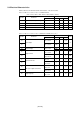
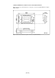

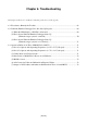
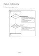
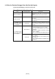
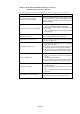
Table Of Contents
- Preface
- Contents
- 1. Precautions for Safety
- 2. Preparation
- 3. Setting Up
- 4. Usage
- 5. Specifications
- 6. Troubleshooting
- 6.1 Flowchart to Remedy the Troubles
- 6.2 When the Emulator Debugger Does Not Start Up Properly
- 6.3 Operation Differs from That of PROM Version MCUs
- (1) Does Not Operate with Operating Frequencies (3.6 V to 5.5 V) Properly
- (2) Does Not Operate with Operating Frequencies (2.7 V to 3.6 V) Properly
- (3) Cannot Reset from Target System
- (4) Data Values of ROM Area at Power-on Are Different
- (5) HOLD* control
- (6) A-D Conversion Values are Different from Expected Values
- (7) Outputs of ALE, Address and Others are Different from Those of Actual MCUs
- 7. Maintenance and Guarantee
( 61 / 78 )
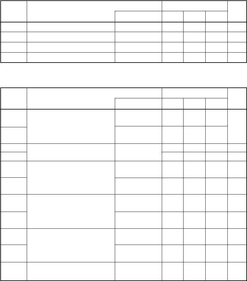
5.4 Electrical Characteristics
Tables 5.10 and 5.11 list IC electrical characteristics of the user interface.
Table 5.10 Electrical characteristics of 74HC4066AFT
(P100 to P107, AN0 to AN7, AN00 to AN07, AN20 to AN27)
Table 5.11 Electrical characteristics of M60081L-0142FP (P00 to P57)
Symbol
Parameter
Max.
1.35
200
Standard values
Unit
Standard
96
10
V
IHC
VILC
RON
RON
Min.
3.15
High level control input voltage
Low level control input voltage
ON resistance
Difference of ON resistances
4.5
4.5
4.5
4.5
V
V
Ω
Ω
V
CC
Symbol
Parameter
VCC = 5.0 V
|IO| < 1 µA
V
CC = 4.5 V
VOL = 0.4 V
V
CC = 4.5 V
VOH = 4.1 V
V
CC = 5.5 V
VI = 0 V
V
CC = 5.5 V
VI = 5.5 V
V
CC = 5.5 V
VO = 0 V
V
CC = 5.5 V
VO = 5.5 V
f = 1 MHz
V
CC = 0 V
Max.
Standard values
Unit
Standard
VIL
Min.
Input voltage
Condition
VCC = 4.5 V
V
CC = 5.5 V
VIH
VOH
VOL
IOL
IOH
IIL
IIH
IOZL
IOZH
CIO
Output voltage
Output current
Input leak current
OFF state output leak current
I/O pin capacity
0
3.85
4.95
8
-1
-1
-1
-1 +1
157
+1
+1
+1
-8
0.05
5.5
1.35
V
V
V
mA
mA
µA
µA
µA
µA
pF