
Emulation Pod User's Manual
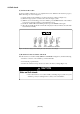
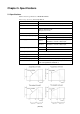
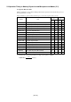
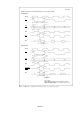
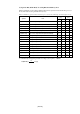
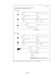
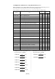
Table Of Contents
- Preface
- Contents
- 1. Precautions for Safety
- 2. Preparation
- 3. Setting Up
- 4. Usage
- 5. Specifications
- 6. Troubleshooting
- 6.1 Flowchart to Remedy the Troubles
- 6.2 When the Emulator Debugger Does Not Start Up Properly
- 6.3 Operation Differs from That of PROM Version MCUs
- (1) Does Not Operate with Operating Frequencies (3.6 V to 5.5 V) Properly
- (2) Does Not Operate with Operating Frequencies (2.7 V to 3.6 V) Properly
- (3) Cannot Reset from Target System
- (4) Data Values of ROM Area at Power-on Are Different
- (5) HOLD* control
- (6) A-D Conversion Values are Different from Expected Values
- (7) Outputs of ALE, Address and Others are Different from Those of Actual MCUs
- 7. Maintenance and Guarantee
( 44 / 78 )
Chapter 5. Specifications
5.1 Specifications
Table 5.1 lists the specifications of M30620T2-RPD-E.
Table 5.1 Specifications of M30620T2-RPD-E
PC4701M, PC4701HS or PC4701L
M16C/62 and M16C/62A Group MCUs (5 V)
M30622SAFP
Single-chip mode
Memory expansion mode
Microprocessor mode
1 MB
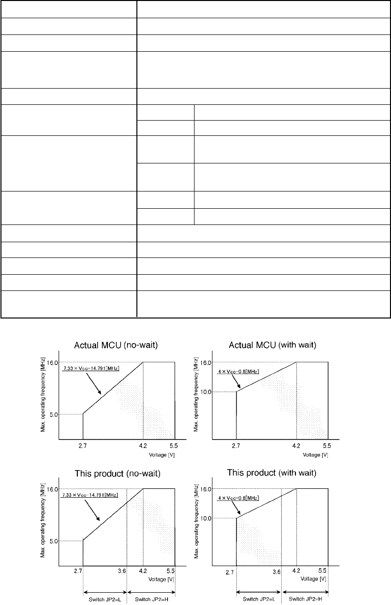
JP2 = L See the charts under this table (2.7 to 3.6 V).
JP2 = H See the charts under this table (3.6 to 5.5 V).
Emulators
Applicable MCUs
Evaluation MCU
Usable modes
Emulation memory
Maximum operating frequency
X
IN
-X
OUT
Internal oscillator circuit board (OSC-3)
Switchable to external oscillator input.
Internal oscillator circuit board
Switchable to external oscillator input.
5 to 35°C (no dew)
-10 to 60°C (no dew)
Supplied from PC4701
Refer to "3.5 Connecting the Target System" (page 35).
• U.S. EMI standards (FCC part 15 Class A)
• CE marking (EN55022, EN50082-1)
Operating voltage
Operating temperature
Storage temperature
Power supply to emulation pod
Connection to target system
Overseas standards
JP2 = L
JP2 = H
2.7 to 3.6 V
3.6 to 5.5 V
Clock supply
X
CIN
-X
COUT