
Emulation Pod User's Manual
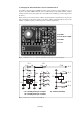
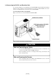
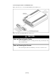
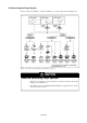

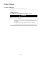
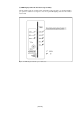
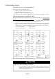
Table Of Contents
- Preface
- Contents
- 1. Precautions for Safety
- 2. Preparation
- 3. Setting Up
- 4. Usage
- 5. Specifications
- 6. Troubleshooting
- 6.1 Flowchart to Remedy the Troubles
- 6.2 When the Emulator Debugger Does Not Start Up Properly
- 6.3 Operation Differs from That of PROM Version MCUs
- (1) Does Not Operate with Operating Frequencies (3.6 V to 5.5 V) Properly
- (2) Does Not Operate with Operating Frequencies (2.7 V to 3.6 V) Properly
- (3) Cannot Reset from Target System
- (4) Data Values of ROM Area at Power-on Are Different
- (5) HOLD* control
- (6) A-D Conversion Values are Different from Expected Values
- (7) Outputs of ALE, Address and Others are Different from Those of Actual MCUs
- 7. Maintenance and Guarantee
( 33 / 78 )
3.4 Connecting the PC4701 and Emulation Pod
To connect the emulation pod to the PC4701, use the FLX120-RPD 120-pin flexible cable included
with this product package. Connect the PC4701 side connector of FLX120-RPD to the cable
connector of the PC4701, then secure with screws the FLX120-RPD.
(1) Connecting the Cable to the PC4701
Figure 3.9 shows how to connect the PC4701 and FLX120-RPD
Figure 3.9 Connecting PC4701 and FLX120-RPD
CAUTION
Note on Connecting the Cable:
• To connect the FLX120-RPD, be sure to hold the both sides of the PC4701 side
connector horizontally with the "UPSIDE" facing up.
• Always shut OFF power before connecting the cable. The power ON state could
destroy internal circuits.
Note on Securing the Screws:
• After connecting the cable to the emulator main unit PC4701, be sure to secure the
screws mounted in both sides of the connector.