
Emulation Pod User's Manual
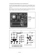
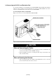
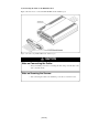
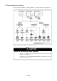

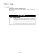
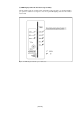
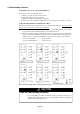
Table Of Contents
- Preface
- Contents
- 1. Precautions for Safety
- 2. Preparation
- 3. Setting Up
- 4. Usage
- 5. Specifications
- 6. Troubleshooting
- 6.1 Flowchart to Remedy the Troubles
- 6.2 When the Emulator Debugger Does Not Start Up Properly
- 6.3 Operation Differs from That of PROM Version MCUs
- (1) Does Not Operate with Operating Frequencies (3.6 V to 5.5 V) Properly
- (2) Does Not Operate with Operating Frequencies (2.7 V to 3.6 V) Properly
- (3) Cannot Reset from Target System
- (4) Data Values of ROM Area at Power-on Are Different
- (5) HOLD* control
- (6) A-D Conversion Values are Different from Expected Values
- (7) Outputs of ALE, Address and Others are Different from Those of Actual MCUs
- 7. Maintenance and Guarantee
( 32 / 78 )
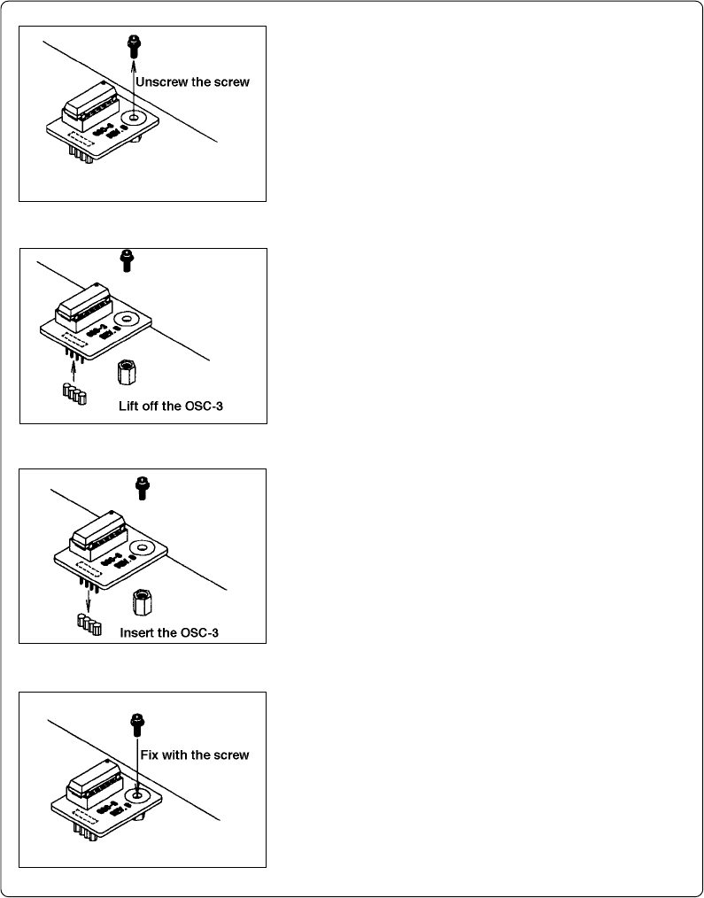
(3) Replacing the Oscillator Circuit Boards
Figure 3.8 shows how to replace the oscillator circuit boards. For the position of the oscillator circuit
board, see Figure 2.2.
Figure 3.8 Replacing the oscillator circuit boards
(3) Attach the J1 connector of another oscillator circuit board
for replacement to the J5 connector of the MCU-dependent
board M30620T2-PRT.
(4) Secure the oscillator circuit board with the screw.
(1) Unscrew the screw connecting the oscillator circuit board.
(2) Lift off the oscillator circuit board.