
Emulation Pod User's Manual
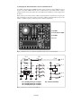
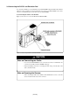
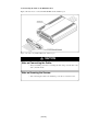
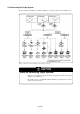

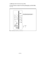
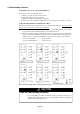
Table Of Contents
- Preface
- Contents
- 1. Precautions for Safety
- 2. Preparation
- 3. Setting Up
- 4. Usage
- 5. Specifications
- 6. Troubleshooting
- 6.1 Flowchart to Remedy the Troubles
- 6.2 When the Emulator Debugger Does Not Start Up Properly
- 6.3 Operation Differs from That of PROM Version MCUs
- (1) Does Not Operate with Operating Frequencies (3.6 V to 5.5 V) Properly
- (2) Does Not Operate with Operating Frequencies (2.7 V to 3.6 V) Properly
- (3) Cannot Reset from Target System
- (4) Data Values of ROM Area at Power-on Are Different
- (5) HOLD* control
- (6) A-D Conversion Values are Different from Expected Values
- (7) Outputs of ALE, Address and Others are Different from Those of Actual MCUs
- 7. Maintenance and Guarantee
( 31 / 78 )
(2) Changing the Internal Oscillator Circuit of Emulation Pod
An oscillator circuit board for 16 MHz is mounted on this product. To use the emulation pod at a
frequency other than 16 MHz, build the desired oscillator circuit on the included OSC-2 oscillator
circuit board (bare board) and replace the board installed in the emulation pod when shipped from
the factory.
Figure 3.6 shows a view of the OSC-2 oscillator circuit board (bare board) and where connector pins
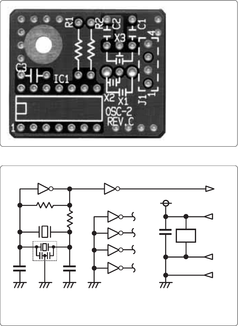
are located. Figure 3.7 shows the circuitry of the OSC-2 oscillator circuit board (bare board). Use the
number of oscillator circuits recommended by the oscillator manufacturer.
Figure 3.6 External view of oscillator board (OSC-2) and connector pin assignment
J1-4: GND
Figure 3.7 Circuit of oscillator board (OSC-2)
J1-3: Oscillator output
J1-2: GND
J1-1: Vcc
* X1: 5.08-mm-pitch 2-pin oscillator IC1: Inverter (Unbuffer)
* X2: 2.54-mm-pitch 2-pin oscillator
* X3: 2.54-mm-pitch 3-pin oscillator
IC1
R1
C2
C1
X1 ,X2
CLK
Vcc
GND
R2
J1-3
1011 8
9
2
1
4
3
6
5
12
13
C3
IC1
J1-1
J1-2
J1-4
GND
IC
1
**
X3
*
IC1
14
7