
Emulation Pod User's Manual
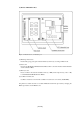
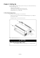
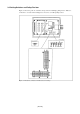
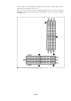
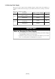
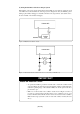
Table Of Contents
- Preface
- Contents
- 1. Precautions for Safety
- 2. Preparation
- 3. Setting Up
- 4. Usage
- 5. Specifications
- 6. Troubleshooting
- 6.1 Flowchart to Remedy the Troubles
- 6.2 When the Emulator Debugger Does Not Start Up Properly
- 6.3 Operation Differs from That of PROM Version MCUs
- (1) Does Not Operate with Operating Frequencies (3.6 V to 5.5 V) Properly
- (2) Does Not Operate with Operating Frequencies (2.7 V to 3.6 V) Properly
- (3) Cannot Reset from Target System
- (4) Data Values of ROM Area at Power-on Are Different
- (5) HOLD* control
- (6) A-D Conversion Values are Different from Expected Values
- (7) Outputs of ALE, Address and Others are Different from Those of Actual MCUs
- 7. Maintenance and Guarantee
( 30 / 78 )
(1) Using the Oscillator Circuit on Target System
When turning on the power supply, the internal clock of emulation pod is selected to supply the clock
to the MCU. To use the external clock on the target system, change the clock by the Init dialog when
starting up the emulator debugger or the CLK command on the script window. (For details, refer to
the user's manual of the emulator debugger)
IMPORTANT
Notes on External Clock:
• To operate the emulation pod with an external clock, construct the oscillator circuit
as shown in Figure 3.4 in the target system and input the oscillator output at 50% duty
(within the operating range of the evaluation MCU) into the XIN pin. And the XOUT
pin should be open.
• Make note of the fact that in the oscillator circuit shown in Figure 3.5 where a
resonator is connected between the XIN and XOUT pins, oscillation does not occur
because a flexible cable, buffer IC and other devices are used between the evaluation
MCU and the target system. It is same for sub-clock oscillator circuits (XCIN and
XCOUT).
Figure 3.4 External oscillator circuit
Figure 3.5 Circuit in which oscillation does not occur (same for XCIN-XCOUT)