
Emulation Pod User's Manual
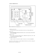
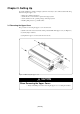
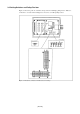
Table Of Contents
- Preface
- Contents
- 1. Precautions for Safety
- 2. Preparation
- 3. Setting Up
- 4. Usage
- 5. Specifications
- 6. Troubleshooting
- 6.1 Flowchart to Remedy the Troubles
- 6.2 When the Emulator Debugger Does Not Start Up Properly
- 6.3 Operation Differs from That of PROM Version MCUs
- (1) Does Not Operate with Operating Frequencies (3.6 V to 5.5 V) Properly
- (2) Does Not Operate with Operating Frequencies (2.7 V to 3.6 V) Properly
- (3) Cannot Reset from Target System
- (4) Data Values of ROM Area at Power-on Are Different
- (5) HOLD* control
- (6) A-D Conversion Values are Different from Expected Values
- (7) Outputs of ALE, Address and Others are Different from Those of Actual MCUs
- 7. Maintenance and Guarantee
( 21 / 78 )
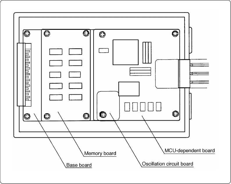
(2) Inside of Emulation Pod
Figure 2.2 Internal view of emulation pod
(1) MCU-dependent board
Board which groups parts (pins and added functions) which vary according to MCU model.
(2) Base board
Board for the M16C/60 and M16C/20 Series MCUs which controls the interface with the PC4701
and the evaluation MCU.
(3) Memory board
Board on which is mounted the emulation memory (1 MB) and the map memory (4 bit × 1 M)
for the M16C/60 and M16C/20 Series MCUs.
(4) Oscillation circuit board
Oscillator circuit board on which the oscillation module device is mounted (16.000 MHz).
It is planned to enable customers to use future M16C/62 and 62A Group models by changing the
MCU-dependent board and MCU board.