
Emulation Pod User's Manual
Table Of Contents
- Preface
- Contents
- 1. Precautions for Safety
- 2. Preparation
- 3. Setting Up
- 4. Usage
- 5. Specifications
- 6. Troubleshooting
- 6.1 Flowchart to Remedy the Troubles
- 6.2 When the Emulator Debugger Does Not Start Up Properly
- 6.3 Operation Differs from That of PROM Version MCUs
- (1) Does Not Operate with Operating Frequencies (3.6 V to 5.5 V) Properly
- (2) Does Not Operate with Operating Frequencies (2.7 V to 3.6 V) Properly
- (3) Cannot Reset from Target System
- (4) Data Values of ROM Area at Power-on Are Different
- (5) HOLD* control
- (6) A-D Conversion Values are Different from Expected Values
- (7) Outputs of ALE, Address and Others are Different from Those of Actual MCUs
- 7. Maintenance and Guarantee
( 20 / 78 )
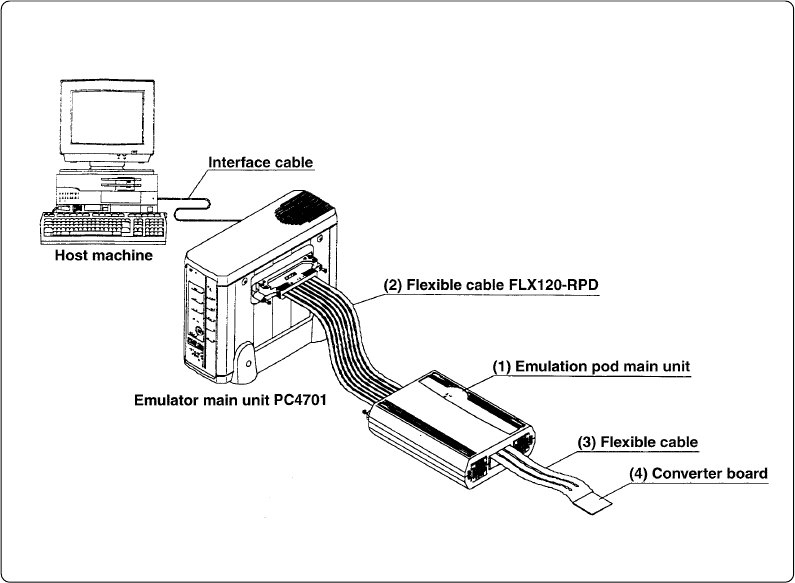
2.4 Name of Each Part
(1) System Configuration
Figure 2.1 System configuration
(1) to (4) in Figure 2.1 are included with this product package.
(1) Emulation pod (M30620T2-RPD-E)
This emulation pod contains an evaluation MCU, emulation memory and circuit to feature the
debugging function.
(2) Flexible cable (FLX120-RPD)
This is a 120-pin flexible cable for connecting the PC4701 emulator and the emulation pod.
(3) Flexible cable (FLX100)
This is a 100-pin flexible cable for connecting the emulation pod and the target system.
(4) Pitch converter board
This is a pitch converter board for connecting to the target system. For details, refer to "3.5
Connecting the Target System" (page 35).