
Datasheet


Section 11 Timer B1
Rev. 2.00 Sep. 23, 2005 Page 155 of 472
REJ09B0160-0200
Bit Bit Name
Initial
Value R/W Description
2
1
0
TMB12
TMB11
TMB10
0
0
0
R/W
R/W
R/W
Clock select
000: Internal
clock: φ/8192
001: Internal clock: φ/2048
010: Internal clock: φ/512
011: Internal clock: φ/256
100: Internal clock: φ/64
101: Internal clock: φ/16
110: Internal clock: φ/4
111: External event (TMIB1): rising or falling edge*
Note: * The edge of the external event signal is selected
by bit IEG1 in the interrupt edge select register 1
(IEGR1). See section 3.2.1, Interrupt Edge
Select Register 1 (IEGR1), for details. Before
setting TMB12 to TMB10 to 1, IRQ1 in the port
mode register 1 (PMR1) should be set to 1.
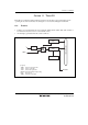
11.3.2 Timer Counter B1 (TCB1)
TCB1 is an 8-bit read-only up-counter, which is incremented by internal clock input. The clock
source for input to this counter is selected by bits TMB12 to TMB10 in TMB1. TCB1 values can
be read by the CPU at any time. When TCB1 overflows from H'FF to H'00 or to the value set in
TLB1, the IRRTB1 flag in IRR2 is set to 1. TCB1 is allocated to the same address as TLB1. TCB1
is initialized to H'00.
11.3.3 Timer Load Register B1 (TLB1)
TLB1 is an 8-bit write-only register for setting the reload value of TCB1. When a reload value is
set in TLB1, the same value is loaded into TCB1 as well, and TCB1 starts counting up from that
value. When TCB1 overflows during operation in auto-reload mode, the TLB1 value is loaded
into TCB1. Accordingly, overflow periods can be set within the range of 1 to 256 input clocks.
TLB1 is allocated to the same address as TCB1. TLB1 is initialized to H'00.