
Datasheet

Section 4 Address Break
Rev. 3.00 Mar. 15, 2006 Page 65 of 526
REJ09B0060-0300
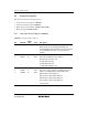
Bit Bit Name
Initial
Value R/W Description
1
0
DCMP1
DCMP0
0
0
R/W
R/W
Data Compare 1 and 0
These bits set the comparison condition between the
data set in BDR and the internal data bus.
00: No data comparison
01: Compares lower 8-bit data between BDRL and
data bus
10: Compares upper 8-bit data between BDRH and
data bus
11: Compares 16-bit data between BDR and data bus
[Legend] x: Don't care.
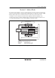
When an address break is set in the data read cycle or data write cycle, the data bus used will
depend on the combination of the byte/word access and address. Table 4.1 shows the access and
data bus used. When an I/O register space with an 8-bit data bus width is accessed in word size, a
byte access is generated twice. For details on data widths of each register, see section 22.1,
Register Addresses (Address Order).
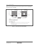
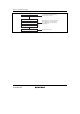
Table 4.1 Access and Data Bus Used
Word Access Byte Access
Even Address
Odd
Address Even Address Odd Address
ROM space Upper 8 bits Lower 8 bits Upper 8 bits Upper 8 bits
RAM space Upper 8 bits Lower 8 bits Upper 8 bits Upper 8 bits
I/O register with 8-bit data
bus width
Upper 8 bits Upper 8 bits Upper 8 bits Upper 8 bits
I/O register with 16-bit data
bus width
Upper 8 bits Lower 8 bits — —