
Datasheet


Section 3 Exception Handling
Rev. 3.00 Mar. 15, 2006 Page 44 of 526
REJ09B0060-0300
3.1 Exception Sources and Vector Address
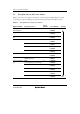
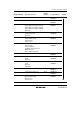
Table 3.1 shows the vector addresses and priority of each exception handling. When more than
one interrupt is requested, handling is performed from the interrupt with the highest priority.
Table 3.1 Exception Sources and Vector Address
Relative Module
Exception Sources
Vector
Number
Vector Address
Priority
RES pin
Watchdog timer
Reset 0 H'000000 to
H'000003
High
Reserved for system use 1 to 6 H'000004 to
H'00001B
External interrupt
pin
NMI 7 H'00001C to
H'00001F
CPU Trap instruction #0 8 H'000020 to
H'000023
Trap instruction #1 9 H'000024 to
H'000027
Trap instruction #2 10 H'000028 to
H'00002B
Trap instruction #3 11 H'00002C to
H'00002F
Address break Break conditions satisfied 12 H'000030 to
H'000033
CPU Direct transition by executing the
SLEEP instruction
13 H'000034 to
H'000037
External interrupt
pin
IRQ0
Low-voltage detection interrupt*
14 H'000038 to
H'00003B
IRQ1 15 H'00003C to
H'00003F
IRQ2 16 H'000040 to
H'000043
IRQ3 17 H'000044 to
H'000047
WKP 18 H'000048 to
H'00004B
Low