
Datasheet


Rev. 3.00 Mar. 15, 2006 Page 519 of 526
REJ09B0060-0300
Item Page Revision (See Manual for Details)
Amended
Bit Bit Name Description
3 STOP Stop Condition Detection Flag
[Setting conditions]
• In master mode, when a stop
condition is detected after frame
transfer
• In slave mode, when a stop
condition is detected after the
general call address or the first
byte slave address, next to
detection of start condition,
accords with the address set in
SAR
18.3.5 I
2
C Bus Status Register
(ICSR)
353
18.7 Usage Note 375 Added
19.3.1 A/D Data Registers A to D
(ADDRA to ADDRD)
380 Amended
…. The temporary register contents are transferred
from the ADDR when the upper byte data is read.
Therefore, byte access to ADDR should be done by
reading the upper byte first then the lower one. Word
access is also possible. ADDR is initialized to H'0000.
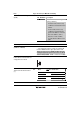
Figure 20.1 Block Diagram of
Power-On Reset Circuit and Low-
Voltage Detection Circuit
392 Amended
RES
C
RES
Amended
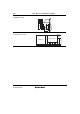
Mode RES Pin Internal State
Active mode 1 Operates
Active mode 2
V
CC
Operates (φ
OSC
/64)
Sleep mode 1 Only timers operate
Sleep mode 2
V
CC
Only timers operate (φ
OSC
/64)
Table 23.2 DC Characteristics (1)
Table 23.11 DC Characteristics
(1)
431,
450