
Datasheet
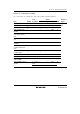

Section 23 Electrical Characteristics
Rev. 3.00 Mar. 15, 2006 Page 431 of 526
REJ09B0060-0300
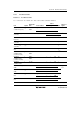
Values
Item Symbol Applicable Pins Test Condition Min. Typ. Max. Unit Notes
Standby
mode
supply
current
I
STBY
V
CC
32-kHz crystal
resonator not
used
5.0 µA *
RAM data
retaining
voltage
V
RAM
V
CC
2.0 V
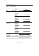
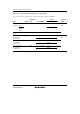
Note: * Pin states during supply current measurement are given below (excluding current in the
pull-up MOS transistors and output buffers).
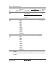
Mode RES Pin Internal State Other Pins Oscillator Pins
Active mode 1 V
CC
Operates V
CC
Main clock:
ceramic or crystal resonator
Active mode 2 Operates
(φ
OSC
/64)
Subclock:
Pin X1 = V
SS
Sleep mode 1 V
CC
Only timers operate V
CC
Sleep mode 2 Only timers operate
(φ
OSC
/64)
Subactive mode V
CC
Operates V
CC
Main clock:
ceramic or crystal resonator
Subsleep mode V
CC
Only timers operate V
CC
Subclock:
crystal resonator
Standby mode V
CC
CPU and timers
both stop
V
CC
Main clock:
ceramic or crystal resonator
Subclock:
Pin X
1 = V
SS