
Datasheet


Section 20 Power-On Reset and Low-Voltage Detection Circuits (Optional)
Rev. 3.00 Mar. 15, 2006 Page 399 of 526
REJ09B0060-0300
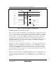
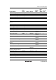
If the power supply voltage (Vcc) falls below Vreset1 (typ. = 2.3 V) voltage, the LVDR function
is performed.
LVDINT
Vcc
Vint (D)
Vint (U)
VSS
LVDDF
LVDUE
LVDUF
IRQ0 interrupt generatedIRQ0 interrupt generated
LVDDE
Vreset1
Figure 20.4 Operational Timing of LVDI Circuit
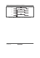
Procedures for Clearing Settings when Using LVDR and LVDI:
To operate or release the low-voltage detection circuit normally, follow the procedure described
below. Figure 20.5 shows the timing for the operation and release of the low-voltage detection
circuit.
1. To operate the low-voltage detection circuit, set the LVDE bit in LVDCR to 1.
2. Wait for 50 µs (t
LVDON
) until the reference voltage and the low-voltage-detection power supply
have stabilized by a software timer, etc. Then, clear the LVDDF and LVDUF bits in LVDSR
to 0 and set the LVDRE, LVDDE, and LVDUE bits in LVDCR to 1, as required.
3. To release the low-voltage detection circuit, start by clearing all of the LVDRE, LVDDE, and
LVDUE bits to 0. Then clear the LVDE bit to 0. The LVDE bit must not be cleared to 0 at the
same timing as the LVDRE, LVDDE, and LVDUE bits because incorrect operation may occur.