
Datasheet


Section 19 A/D Converter
Rev. 3.00 Mar. 15, 2006 Page 383 of 526
REJ09B0060-0300
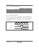
Bit Bit Name
Initial
Value R/W Description
7 TRGE 0 R/W Trigger Enable
A/D conversion is started at the falling edge and the
rising edge of the external trigger signal (ADTRG) when
this bit is set to 1.
The selection between the falling edge and rising edge
of the external trigger pin (ADTRG) conforms to the
WPEG5 bit in the interrupt edge select register 2
(IEGR2)
6 to 4 — All 1 — Reserved
These bits are always read as 1.
3, 2 — All 0 R/W Reserved
Although these bits are readable/writable, these bits
should not be set to 1.
1 — 1 — Reserved
This bit is always read as 1.
0 — 0 R/W Reserved
Although this bit is readable/writable, this bit should not
be set to 1.