
Datasheet


Section 19 A/D Converter
Rev. 3.00 Mar. 15, 2006 Page 377 of 526
REJ09B0060-0300
Section 19 A/D Converter
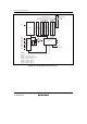
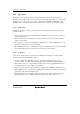
This LSI includes a successive approximation type 10-bit A/D converter that allows up to eight
analog input channels to be selected. The block diagram of the A/D converter is shown in figure
19.1.
19.1 Features
• 10-bit resolution
• Eight input channels
• Conversion time: at least 3.5 µs per channel
(at 20-MHz operation)
• Two operating modes
Single mode: Single-channel A/D conversion
Scan mode: Continuous A/D conversion on 1 to 4 channels
• Four data registers
Conversion results are held in a data register for each channel
• Sample-and-hold function
• Two conversion start methods
Software
External trigger signal
• Interrupt source
An A/D conversion end interrupt (ADI) request can be generated