
Datasheet


Section 18 I
2
C Bus Interface 2 (IIC2)
Rev. 3.00 Mar. 15, 2006 Page 349 of 526
REJ09B0060-0300
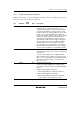
Bit Bit Name
Initial
Value R/W Description
6 WAIT 0 R/W Wait Insertion Bit
In master mode with the I
2
C bus format, this bit selects
whether to insert a wait after data transfer except the
acknowledge bit. When WAIT is set to 1, after the fall of
the clock for the final data bit, low period is extended for
two transfer clocks. If WAIT is cleared to 0, data and
acknowledge bits are transferred consecutively with no
wait inserted.
The setting of this bit is invalid in slave mode with the
I
2
C bus format or with the clocked synchronous serial
format.
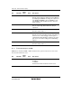
5
4
1
1
Reserved
These bits are always read as 1.
3 BCWP 1 R/W BC Write Protect
This bit controls the BC2 to BC0 modifications. When
modifying BC2 to BC0, this bit should be cleared to 0
and use the MOV instruction. In clock synchronous
serial mode, BC should not be modified.
0: When writing, values of BC2 to BC0 are set.
1: When reading, 1 is always read.
When writing, settings of BC2 to BC0 are invalid.
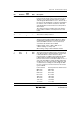
2
1
0
BC2
BC1
BC0
0
0
0
R/W
R/W
R/W
Bit Counter 2 to 0
These bits specify the number of bits to be transferred
next. When read, the remaining number of transfer bits
is indicated. With the I
2
C bus format, the data is
transferred with one addition acknowledge bit. Bit BC2
to BC0 settings should be made during an interval
between transfer frames. If bits BC2 to BC0 are set to a
value other than 000, the setting should be made while
the SCL pin is low. The value returns to 000 at the end
of a data transfer, including the acknowledge bit. With
the clock synchronous serial format, these bits should
not be modified.
I
2
C Bus Format Clock Synchronous Serial Format
000: 9 bits 000: 8 bits
001: 2 bits 001: 1 bits
010: 3 bits 010: 2 bits
011: 4 bits 011: 3 bits
100: 5 bits 100: 4 bits
101: 6 bits 101: 5 bits
110: 7 bits 110: 6 bits
111: 8 bits 111: 7 bits