
Datasheet

Section 17 Serial Communication Interface 3 (SCI3)
Rev. 3.00 Mar. 15, 2006 Page 335 of 526
REJ09B0060-0300
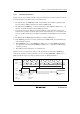
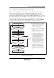
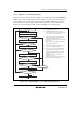
17.6.2 Multiprocessor Serial Data Reception
Figure 17.17 shows a sample flowchart for multiprocessor serial data reception. If the MPIE bit in
SCR3 is set to 1, data is skipped until data with a 1 multiprocessor bit is sent. On receiving data
with a 1 multiprocessor bit, the receive data is transferred to RDR. An RXI interrupt request is
generated at this time. All other SCI3 operations are the same as those in asynchronous mode.
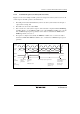
Figure 17.18 shows an example of SCI3 operation for multiprocessor format reception.
Yes
<End>
No
Start reception
No
Yes
[4]
Clear RE bit in SCR3 to 0
Error processing
(Continued on
next page)
[5]
Yes
No
FER+OER = 1
RDRF = 1
All data received?
Set MPIE bit in SCR3 to 1
[1]
[2]
Read OER and FER flags in SSR
Read RDRF flag in SSR [3]
Read receive data in RDR
No
Yes
[A]
This station's ID?
Read OER and FER flags in SSR
Yes
No
Read RDRF flag in SSR
No
Yes
FER+OER = 1
Read receive data in RDR
RDRF = 1
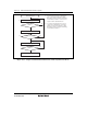
[1] Set the MPIE bit in SCR3 to 1.
[2] Read OER and FER in SSR to check for
errors. Receive error processing is performed
in cases where a receive error occurs.
[3] Read SSR and check that the RDRF flag is
set to 1, then read the receive data in RDR
and compare it with this station’s ID.
If the data is not this station’s ID, set the MPIE
bit to 1 again.
When data is read from RDR, the RDRF flag
is automatically cleared to 0.
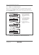
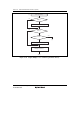
[4] Read SSR and check that the RDRF flag is
set to 1, then read the data in RDR.
[5] If a receive error occurs, read the OER and
FER flags in SSR to identify the error. After
performing the appropriate error processing,
ensure that the OER and FER flags are all
cleared to 0.
Reception cannot be resumed if either of
these flags is set to 1.
In the case of a framing error, a break can be
detected by reading the RxD pin value.
Figure 17.17 Sample Multiprocessor Serial Reception Flowchart (1)