
Datasheet

Section 17 Serial Communication Interface 3 (SCI3)
Rev. 3.00 Mar. 15, 2006 Page 329 of 526
REJ09B0060-0300
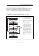
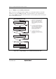
17.5.4 Serial Data Reception (Clocked Synchronous Mode)
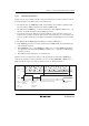
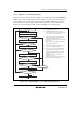
Figure 17.12 shows an example of SCI3 operation for reception in clocked synchronous mode. In
serial reception, the SCI3 operates as described below.
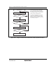
1. The SCI3 performs internal initialization synchronous with a synchronization clock input or
output, starts receiving data.
2. The SCI3 stores the receive data in RSR.
3. If an overrun error occurs (when reception of the next data is completed while the RDRF flag
in SSR is still set to 1), the OER bit in SSR is set to 1. If the RIE bit in SCR3 is set to 1 at this
time, an ERI interrupt request is generated, receive data is not transferred to RDR, and the
RDRF flag remains to be set to 1.
4. If reception is completed successfully, the RDRF bit in SSR is set to 1, and receive data is
transferred to RDR. If the RIE bit in SCR3 is set to 1 at this time, an RXI interrupt request is
generated.
Serial
clock
Serial
data
1 frame
1 frame
Bit 0Bit 7 Bit 7 Bit 0 Bit 1 Bit 6 Bit 7
RDRF
OER
LSI
operation
User
processing
RXI interrupt request generated
RDR data read
RDRF flag
cleared
to 0
RXI interrupt
request
generated
ERI interrupt request
generated by
overrun error
Overrun error
processing
RDR data has
not been read
(RDRF = 1)
Figure 17.12 Example of SCI3 Reception in Clocked Synchronous Mode