
Datasheet

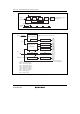

Section 17 Serial Communication Interface 3 (SCI3)
Rev. 3.00 Mar. 15, 2006 Page 305 of 526
REJ09B0060-0300
Bit Bit Name
Initial
Value R/W Description
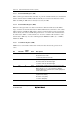
3 STOP 0 R/W Stop Bit Length (enabled only in asynchronous mode)
Selects the stop bit length in transmission.
0: 1 stop bit
1: 2 stop bits
For reception, only the first stop bit is checked,
regardless of the value in the bit. If the second stop bit
is 0, it is treated as the start bit of the next transmit
character.
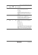
2 MP 0 R/W Multiprocessor Mode
When this bit is set to 1, the multiprocessor
communication function is enabled. The PE bit and PM
bit settings are invalid in multiprocessor mode. In
clocked synchronous mode, clear this bit to 0.
1
0
CKS1
CKS0
0
0
R/W
R/W
Clock Select 0 and 1
These bits select the clock source for the baud rate
generator.
00: φ clock (n = 0)
01: φ/4 clock (n = 1)
10: φ/16 clock (n = 2)
11: φ/64 clock (n = 3)
For the relationship between the bit rate register setting
and the baud rate, see section 17.3.8, Bit Rate Register
(BRR). n is the decimal representation of the value of n
in BRR (see section 17.3.8, Bit Rate Register (BRR)).