
Datasheet


Section 16 14-Bit PWM
Rev. 3.00 Mar. 15, 2006 Page 295 of 526
REJ09B0060-0300
Section 16 14-Bit PWM
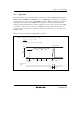
The 14-bit PWM is a pulse division type PWM that can be used for electronic tuner control, etc.
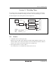
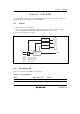
Figure 16.1 shows a block diagram of the 14-bit PWM.
16.1 Features
• Choice of two conversion periods
A conversion period of 32768/φ with a minimum modulation width of 2/φ, or a conversion
period of 16384/φ with a minimum modulation width of 1/φ, can be selected.
• Pulse division method for less ripple
PWCR: PWM control register
[Legend]
Internal data bus
PWDRL: PWM data register L
PWDRU: PWM data register U
PWM: PWM output pin
PWCR
PWDRL
PWDRU
PWM
PWM waveform
generator
φ/4
φ/2
Figure 16.1 Block Diagram of 14-Bit PWM
16.2 Input/Output Pin
Table 16.1 shows the 14-bit PWM pin configuration.
Table 16.1 Pin Configuration
Name Abbreviation I/O Function
14-bit PWM square-wave output PWM Output 14-bit PWM square-wave output pin