
Datasheet

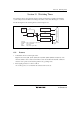


Section 15 Watchdog Timer
Rev. 3.00 Mar. 15, 2006 Page 293 of 526
REJ09B0060-0300
15.3 Operation
The watchdog timer is provided with an 8-bit counter. If 1 is written to WDON while writing 0 to
B2WI when the TCSRWE bit in TCSRWD is set to 1, TCWD begins counting up. (To operate the
watchdog timer, two write accesses to TCSRWD are required.) When a clock pulse is input after
the TCWD count value has reached H'FF, the watchdog timer overflows and an internal reset
signal is generated. The internal reset signal is output for a period of 256 φ
osc
clock cycles. TCWD
is a writable counter, and when a value is set in TCWD, the count-up starts from that value. An
overflow period in the range of 1 to 256 input clock cycles can therefore be set, according to the
TCWD set value.
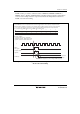
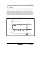
Figure 15.2 shows an example of watchdog timer operation.
Example: With 30ms overflow period when φ = 4 MHz
4 × 10
6
× 30 × 10
–3
= 14.6
8192
TCWD overflow
H'FF
H'00
Internal reset
signal
H'F1
TCWD
count value
H'F1 written
to TCWD
H'F1 written to TCWD Reset generated
Start
256 φ
osc
clock cycles
Therefore, 256 – 15 = 241 (H'F1) is set in TCW.
Figure 15.2 Watchdog Timer Operation Example