
Datasheet

Section 14 Timer Z
Rev. 3.00 Mar. 15, 2006 Page 278 of 526
REJ09B0060-0300
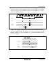
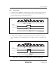
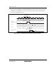
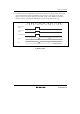
4. Output Inverse Timing by POCR: The output level can be inverted by inverting the POLD,
POLC, and POLB bits in POCR in PWM mode. Figure 14.47 shows the timing.
T
1
T
2
TFCR
Address bus
POCR address
Timer Z
output pin
Inverted
φ
Figure 14.47 Example of Output Inverse Timing of Timer Z by Writing to POCR
14.5 Interrupts
There are three kinds of timer Z interrupt sources; input capture/compare match, overflow, and
underflow. An interrupt is requested when the corresponding interrupt request flag is set to 1 while
the corresponding interrupt enable bit is set to 1.
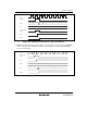
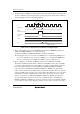
14.5.1 Status Flag Set Timing
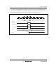
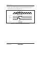
1. IMF Flag Set Timing: The IMF flag is set to 1 by the compare match signal that is generated
when the GR matches with the TCNT. The compare match signal is generated at the last state
of matching (timing to update the counter value when the GR and TCNT match). Therefore,
when the TCNT and GR matches, the compare match signal will not be generated until the
TCNT input clock is generated. Figure 14.48 shows the timing to set the IMF flag.