
Datasheet

Section 14 Timer Z
Rev. 3.00 Mar. 15, 2006 Page 274 of 526
REJ09B0060-0300
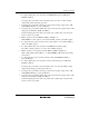
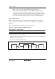
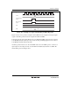
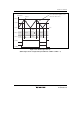
Figures 14.42 and 14.43 show the operation examples when buffer operation has been designated
for GRB_0 and GRD_0 in complementary PWM mode. These are examples when a PWM
waveform of 0% duty is created by using the buffer operation and performing GRD_0 ≥ GRA_0.
Data is transferred from GRD_0 to GRB_0 according to the settings of CMD_0 and CMD_1 when
TCNT_0 and GRA_0 are compared and their contents match or when TCNT_1 underflows.
However, when GRD_0 ≥ GRA_0, data is transferred from GRD_0 to GRB_0 when TCNT_1
underflows regardless of the setting of CMD_0 and CMD_1. When GRD_0 = H'0000, data is
transferred from GRD_0 to GRB_0 when TCNT_0 and GRA_0 are compared and their contents
match regardless of the settings of CMD_0 and CMD_1.
GRA_0
H'0000
H'0999
FTIOB0
FTIOD0
TCNT_0
TCNT values
Time
GRB_0 (When restored, data will be transferred
to the saved location regardless of the
CMD1 and CMD0 values)
TCNT_1
H'0999
H'0999
H'0999
H'0999
H'1FFF
H'0999
GRD_0
H'1FFF
GRB_0
Figure 14.42 Buffer Operation (3)
(Buffer Operation in Complementary PWM Mode CMD1 = CMD0 = 1)