
Datasheet

Section 14 Timer Z
Rev. 3.00 Mar. 15, 2006 Page 269 of 526
REJ09B0060-0300
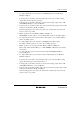
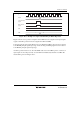
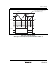
2. When GR is an input capture register
When an input capture occurs, the value in TCNT is transferred to the general register and the
value previously stored in the general register is transferred to the buffer register.
This operation is illustrated in figure 14.36.
TCNT
Buffer register
General
register
Input capture
signal
Figure 14.36 Input Capture Buffer Operation
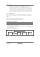
3. Complementary PWM Mode
When the counter switches from counting up to counting down or vice versa, the value of the
buffer register is transferred to the general register. Here, the value of the buffer register is
transferred to the general register in the following timing:
A. When TCNT_0 and GRA_0 are compared and their contents match
B. When TCNT_1 underflows
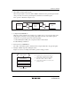
4. Reset Synchronous PWM Mode
The value of the buffer register is transferred from compare match A0 to the general register.
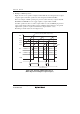
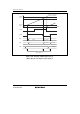
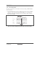
5. Example of Buffer Operation Setting Procedure
Figure 14.37 shows an example of the buffer operation setting procedure.
[1] Designate GR as an input capture register or
output compare register by means of TIOR.
[2] Designate GR for buffer operation with bits
BFD1, BFC1, BFD0, or BFC0 in TMDR.
[3] Set the STR bit in TSTR to 1 to start the count
operation of TCNT.
[1]
[2]
[3]
Select GR function
Set buffer operation
Start count operation
Buffer operation
<Buffer operation>
Figure 14.37 Example of Buffer Operation Setting Procedure