
Datasheet

Section 14 Timer Z
Rev. 3.00 Mar. 15, 2006 Page 265 of 526
REJ09B0060-0300
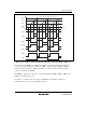
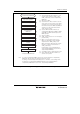
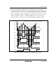
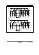
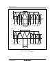
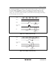
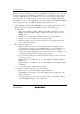
In complementary PWM mode, when the counter switches from up-counter to down-counter or
vice versa, TCNT_0 and TCNT_1 overshoots or undershoots, respectively. In this case, the
conditions to set the IMFA flag in channel 0 and the UDF flag in channel 1 differ from usual
settings. Also, the transfer conditions in buffer operation differ from usual settings. Such timings
are shown in figures 14.33 and 14.34.
GR
Buffer transfer
signal
Set to 1
Flag is not set
Transferred
to buffer
Not transferred
to buffer
N+1
GRA_0
TCNT
N
N-1 N-1N
N
IMFA
Figure 14.33 Timing of Overshooting
H'FFFFH'0001 H'0001H'0000H'0000
GR
UDF
TCNT
Buffer transfer
signal
Set to 1
Flag is not set
Transferred
to buffer
Not transferred
to buffer
Figure 14.34 Timing of Undershooting