
Datasheet

Section 14 Timer Z
Rev. 3.00 Mar. 15, 2006 Page 261 of 526
REJ09B0060-0300
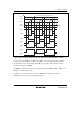
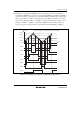
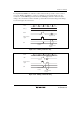
2. Examples of Complementary PWM Mode Operation: Figure 14.31 shows an example of
complementary PWM mode operation. In complementary PWM mode, TCNT_0 and TCNT_1
perform an increment or decrement operation. When TCNT_0 and GRA_0 are compared and
their contents match, the counter is decremented, and when TCNT_1 underflows, the counter
is incremented. In GRA_0, GRA_1, and GRB_1, compare match is carried out in the order of
TCNT_0 → TCNT_1 → TCNT_1 → TCNT_0 and PWM waveform is output, during one
cycle of an up/down counter. In this mode, the initial setting will be TCNT_0 > TCNT_1.
GRA_0
GRB_0
GRA_1
GRB_1
TCNT values
TCNT_0 and GRA_0 are compared and their contents match
Time
H'0000
FTIOA1
FTIOB1
FTIOB0
FTIOC1
FTIOD1
FTIOC0
FTIOD0
Figure 14.31 Example of Complementary PWM Mode Operation (1)