
Datasheet

Section 14 Timer Z
Rev. 3.00 Mar. 15, 2006 Page 255 of 526
REJ09B0060-0300
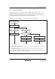
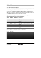
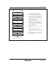
[1] Clear bit STR0 in TSTR to 0 and stop the
counter operation of TCNT_0. Set reset
synchronous PWM mode after TCNT_0 stops.
[2] Select the counter clock with bits TPSC2 to
TOSC0 in TCR. When an external clock is
selected, select the external clock edge with bits
CKEG1 and CKEG0 in TCR.
[3] Use bits CCLR1 and CCLR0 in TCR to select
counter clearing source GRA_0.
[4] Select the reset synchronous PWM mode with
bits CMD1 and CMD0 in TFCR. FTIOB0 to
FTIOD0 and FTIOA1 to FTIOD1 become PWM
output pins automatically.
[5] Set H'00 to TOCR.
[6] Set TCNT_0 as H'0000. TCNT1 does not need
to be set.
[7] GRA_0 is a cycle register. Set a cycle for
GRA_0. Set the changing point timing of the
PWM output waveform for GRB_0, GRA_1, and
GRB_1.
[8] Enable or disable the timer output by TOER.
[9] Set the STR bit in TSTR to 1 and start the
counter operation.
[1]
Reset synchronous PWM mode
[2]
Stop counter operation
[3]
Select counter clock
[4]
Select counter clearing source
[5]
Set reset synchronous
PWM mode
[6]
Initialize the output pin
[7]
Set TCNT
[8]
Set GR
[9]Start counter operation
Enable waveform output
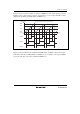
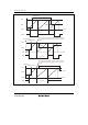
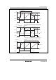
<Reset synchronous PWM mode>
Figure 14.26 Example of Reset Synchronous PWM Mode Setting Procedure