
Datasheet

Section 14 Timer Z
Rev. 3.00 Mar. 15, 2006 Page 251 of 526
REJ09B0060-0300
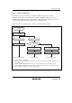
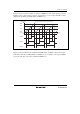
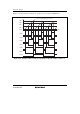
Figure 14.23 shows another example of operation in PWM mode. The output signals go to 0 and
TCNT is reset at compare match A, and the output signals go to 1 at compare match B, C, and D
(TOB, TOC, and TOD = 0, POLB, POLC, and POLD = 1).
GRA
GRB
GRC
GRD
H'0000
FTIOC
FTIOD
FTIOB
Counter cleared by GRA compare match
Time
TCNT value
Figure 14.23 Example of PWM Mode Operation (2)
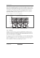
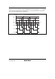
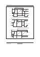
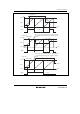
Figures 14.24 (when TOB, TOC, and TOD = 0, POLB, POLC, and POLD = 0) and 14.25 (when
TOB, TOC, and TOD = 0, POLB, POLC, and POLD = 1) show examples of the output of PWM
waveforms with duty cycles of 0% and 100% in PWM mode.