
Datasheet


Section 14 Timer Z
Rev. 3.00 Mar. 15, 2006 Page 232 of 526
REJ09B0060-0300
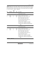
14.3.11 Timer Status Register (TSR)
TSR indicates generation of an overflow/underflow of TCNT and a compare match/input capture
of GRA, GRB, GRC, and GRD. These flags are interrupt sources. If an interrupt is enabled by a
corresponding bit in TIER, TSR requests an interrupt for the CPU. Timer Z has two TSR registers,
one for each channel.
Bit Bit Name
Initial
Value R/W Description
7, 6 All 1 Reserved
These bits are always read as 1.
5 UDF* 0 R/W Underflow Flag
[Setting condition]
• When TCNT_1 underflows
[Clearing condition]
• When 0 is written to UDF after reading UDF = 1
4 OVF 0 R/W Overflow Flag
[Setting condition]
• When the TCNT value underflows
[Clearing condition]
• When 0 is written to OVF after reading OVF = 1
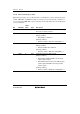
3 IMFD 0 R/W Input Capture/Compare Match Flag D
[Setting conditions]
• When TCNT = GRD and GRD is functioning as
output compare register
• When TCNT value is transferred to GRD by input
capture signal and GRD is functioning as input
capture register
[Clearing condition]
• When 0 is written to IMFD after reading IMFD = 1