
Datasheet


Section 14 Timer Z
Rev. 3.00 Mar. 15, 2006 Page 230 of 526
REJ09B0060-0300
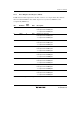
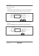
14.3.10 Timer I/O Control Register (TIORA and TIORC)
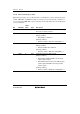
The TIOR registers control the general registers (GR). Timer Z has four TIOR registers
(TIORA_0, TIORA_1, TIORC_0, and TIORC_1), two for each channel. In PWM mode including
complementary PWM mode and reset synchronous PWM mode, the settings of TIOR are invalid.
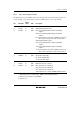
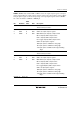
TIORA: TIORA selects whether GRA or GRB is used as an output compare register or an input
capture register. When an output compare register is selected, the output setting is selected. When
an input capture register is selected, an input edge of an input capture signal is selected. TIORA
also selects the function of FTIOA or FTIOB pin.
Bit Bit Name
Initial
Value R/W Description
7 1 Reserved
This bit is always read as 1.
6
5
4
IOB2
IOB1
IOB0
0
0
0
R/W
R/W
R/W
I/O Control B2 to B0
GRB is an output compare register:
000: Disables pin output by compare match
001: 0 output by GRB compare match
010: 1 output by GRB compare match
011: Toggle output by GRB compare match
GRB is an input capture register:
100: Input capture to GRB at the rising edge
101: Input capture to GRB at the falling edge
11X: Input capture to GRB at both rising and falling
edges
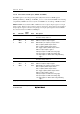
3 1 Reserved
This bit is always read as 1.
2
1
0
IOA2
IOA1
IOA0
0
0
0
R/W
R/W
R/W
I/O Control A2 to A0
GRA is an output compare register:
000: Disables pin output by compare match
001: 0 output by GRA compare match
010: 1 output by GRA compare match
011: Toggle output by GRA compare match
GRA is an input capture register:
100: Input capture to GRA at the rising edge
101: Input capture to GRA at the falling edge
11X: Input capture to GRA at both rising and falling
edges
[Legend] X: Don't care