
Datasheet


Section 14 Timer Z
Rev. 3.00 Mar. 15, 2006 Page 224 of 526
REJ09B0060-0300
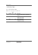
Bit Bit Name
Initial
Value R/W Description
1
0
CMD1
CMD0
0
0
R/W
R/W
Combination Mode 1 and 0
00: Channel 0 and channel 1 operate normally
01: Channel 0 and channel 1 are used together to
operate in reset synchronous PWM mode
10: Channel 0 and channel 1 are used together to
operate in complementary PWM mode (transferred
at the trough)
11: Channel 0 and channel 1 are used together to
operate in complementary PWM mode (transferred
at the crest)
Note: When reset synchronous PWM mode or
complementary PWM mode is selected by these
bits, this setting has the priority to the settings for
PWM mode by each bit in TPMR. Stop TCNT_0
and TCNT_1 before making settings for reset
synchronous PWM mode or complementary
PWM mode.
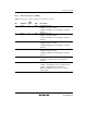
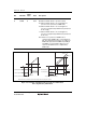
TCNT_0
Normal phase
Counter phase
Normal phase
Counter phase
Active level
Active level
Active level
Active level
Complementary PWM mode
Note: Write H'00 to TOCR to start initial outputs after stopping the counter.
Reset synchronous PWM mode
Initial
output
Initial
output
TCNT_1
Figure 14.4 Example of Outputs in Reset Synchronous PWM Mode
and Complementary PWM Mode