
Datasheet


Section 14 Timer Z
Rev. 3.00 Mar. 15, 2006 Page 223 of 526
REJ09B0060-0300
14.3.4 Timer Function Control Register (TFCR)
TFCR selects the settings and output levels for each operating mode.
Bit Bit Name
Initial
Value R/W Description
7 1 Reserved
This bit is always read as 1.
6 STCLK 0 R/W External Clock Input Select
0: External clock input is disabled
1: External clock input is enabled
5 ADEG 0 R/W A/D Trigger Edge Select
A/D module should be set to start an A/D conversion by
the external trigger
0: A/D trigger at the crest in complementary PWM mode
1: A/D trigger at the trough in complementary PWM
mode
4 ADTRG 0 R/W External Trigger Disable
0: A/D trigger for PWM cycles is disabled in
complementary PWM mode
1: A/D trigger for PWM cycles is enabled in
complementary PWM mode
3 OLS1 0 R/W Output Level Select 1
Selects the counter-phase output levels in reset
synchronous PWM mode or complementary PWM
mode.
0: Initial output is high and the active level is low.
1: Initial output is low and the active level is high.
2 OLS0 0 R/W Output Level Select 0
Selects the normal-phase output levels in reset
synchronous PWM mode or complementary PWM
mode.
0: Initial output is high and the active level is low.
1: Initial output is low and the active level is high.
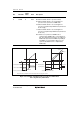
Figure 14.4 shows an example of outputs in reset
synchronous PWM mode and complementary PWM
mode when OLS1 = 0 and OLS0 = 0.