
Datasheet


Section 13 Timer W
Rev. 3.00 Mar. 15, 2006 Page 206 of 526
REJ09B0060-0300
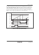
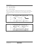
13.5.3 Input Capture Timing
Input capture on the rising edge, falling edge, or both edges can be selected through settings in
TIOR0 and TIOR1. Figure 13.17 shows the timing when the falling edge is selected. The pulse
width of the input capture signal must be at least two system clock (φ) cycles; shorter pulses will
not be detected correctly.
TCNT
Input capture
input
φ
N–1
N N+1 N+2
N
GRA to GRD
Input capture
signal
Figure 13.17 Input Capture Input Signal Timing
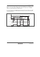
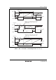
13.5.4 Timing of Counter Clearing by Compare Match
Figure 13.18 shows the timing when the counter is cleared by compare match A. When the GRA
value is N, the counter counts from 0 to N, and its cycle is N + 1.
TCNT
Compare
match signal
φ
GRA
N
N H'0000
Figure 13.18 Timing of Counter Clearing by Compare Match