
Datasheet


Section 13 Timer W
Rev. 3.00 Mar. 15, 2006 Page 182 of 526
REJ09B0060-0300
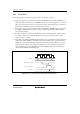
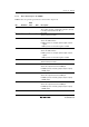
Table 13.1 summarizes the timer W functions, and figure 13.1 shows a block diagram of timer W.
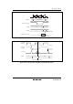
Table 13.1 Timer W Functions
Input/Output Pins
Item Counter FTIOA FTIOB FTIOC FTIOD
Count clock Internal clocks: φ, φ/2, φ/4, φ/8
External clock: FTCI
General registers
(output compare/input
capture registers)
Period
specified in
GRA
GRA GRB GRC (buffer
register for
GRA in
buffer mode)
GRD (buffer
register for
GRB in
buffer mode)
Counter clearing function GRA
compare
match
GRA
compare
match
— — —
Initial output value
setting function
—
Yes Yes Yes Yes
Buffer function
—
Yes Yes
—
—
Compare 0 —
Yes Yes
Yes Yes
match output
1 —
Yes Yes
Yes Yes
Toggle —
Yes Yes
Yes Yes
Input capture function —
Yes Yes Yes
Yes
PWM mode —
—
Yes Yes
Yes
Interrupt sources Overflow Compare
match/input
capture
Compare
match/input
capture
Compare
match/input
capture
Compare
match/input
capture