
Datasheet


Section 12 Timer V
Rev. 3.00 Mar. 15, 2006 Page 173 of 526
REJ09B0060-0300
12.4 Operation
12.4.1 Timer V Operation
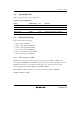
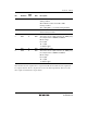
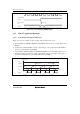
1. According to table 12.2, six internal/external clock signals output by prescaler S can be
selected as the timer V operating clock signals. When the operating clock signal is selected,
TCNTV starts counting-up. Figure 12.2 shows the count timing with an internal clock signal
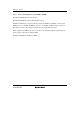
selected, and figure 12.3 shows the count timing with both edges of an external clock signal
selected.
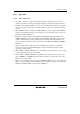
2. When TCNTV overflows (changes from H'FF to H'00), the overflow flag (OVF) in TCRV0
will be set. The timing at this time is shown in figure 12.4. An interrupt request is sent to the
CPU when OVIE in TCRV0 is 1.
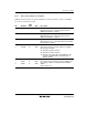
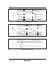
3. TCNTV is constantly compared with TCORA and TCORB. Compare match flag A or B
(CMFA or CMFB) is set to 1 when TCNTV matches TCORA or TCORB, respectively. The
compare-match signal is generated in the last state in which the values match. Figure 12.5
shows the timing. An interrupt request is generated for the CPU when CMIEA or CMIEB in
TCRV0 is 1.
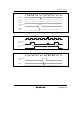
4. When a compare match A or B is generated, the TMOV responds with the output value
selected by bits OS3 to OS0 in TCSRV. Figure 12.6 shows the timing when the output is
toggled by compare match A.
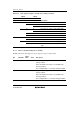
5. When CCLR1 or CCLR0 in TCRV0 is 01 or 10, TCNTV can be cleared by the corresponding
compare match. Figure 12.7 shows the timing.
6. When CCLR1 or CCLR0 in TCRV0 is 11, TCNTV can be cleared by the rising edge of the
input of TMRIV pin. A TMRIV input pulse-width of at least 1.5 system clocks is necessary.
Figure 12.8 shows the timing.
7. When a counter-clearing source is generated with TRGE in TCRV1 set to 1, the counting-up is
halted as soon as TCNTV is cleared. TCNTV resumes counting-up when the edge selected by
TVEG1 or TVEG0 in TCRV1 is input from the TGRV pin.