
Datasheet


Section 12 Timer V
Rev. 3.00 Mar. 15, 2006 Page 172 of 526
REJ09B0060-0300
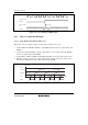
12.3.5 Timer Control Register V1 (TCRV1)
TCRV1 selects the edge at the TRGV pin, enables TRGV input, and selects the clock input to
TCNTV.
Bit Bit Name
Initial
Value R/W Description
7 to 5 All 1 Reserved
These bits are always read as 1.
4
3
TVEG1
TVEG0
0
0
R/W
R/W
TRGV Input Edge Select
These bits select the TRGV input edge.
00: TRGV trigger input is prohibited
01: Rising edge is selected
10: Falling edge is selected
11: Rising and falling edges are both selected
2 TRGE 0 R/W TCNT starts counting up by the input of the edge which
is selected by TVEG1 and TVEG0.
0: Disables starting counting-up TCNTV by the input of
the TRGV pin and halting counting-up TCNTV when
TCNTV is cleared by a compare match.
1: Enables starting counting-up TCNTV by the input of
the TRGV pin and halting counting-up TCNTV when
TCNTV is cleared by a compare match.
1 1 Reserved
This bit is always read as 1.
0 ICKS0 0 R/W Internal Clock Select 0
This bit selects clock signals to input to TCNTV in
combination with CKS2 to CKS0 in TCRV0.
Refer to table 12.2.