
Datasheet


Section 12 Timer V
Rev. 3.00 Mar. 15, 2006 Page 165 of 526
REJ09B0060-0300
Section 12 Timer V
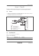
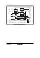
Timer V is an 8-bit timer based on an 8-bit counter. Timer V counts external events. Compare-
match signals with two registers can also be used to reset the counter, request an interrupt, or
output a pulse signal with an arbitrary duty cycle. Counting can be initiated by a trigger input at
the TRGV pin, enabling pulse output control to be synchronized to the trigger, with an arbitrary
delay from the trigger input. Figure 12.1 shows a block diagram of timer V.
12.1 Features
• Choice of seven clock signals is available.
Choice of six internal clock sources (φ/128, φ/64, φ/32, φ/16, φ/8, φ/4) or an external clock.
• Counter can be cleared by compare match A or B, or by an external reset signal. If the count
stop function is selected, the counter can be halted when cleared.
• Timer output is controlled by two independent compare match signals, enabling pulse output
with an arbitrary duty cycle, PWM output, and other applications.
• Three interrupt sources: compare match A, compare match B, timer overflow
• Counting can be initiated by trigger input at the TRGV pin. The rising edge, falling edge, or
both edges of the TRGV input can be selected.