
Datasheet


Section 11 Timer B1
Rev. 3.00 Mar. 15, 2006 Page 163 of 526
REJ09B0060-0300
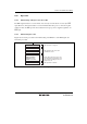
11.3.2 Timer Counter B1 (TCB1)
TCB1 is an 8-bit read-only up-counter, which is incremented by internal clock input. The clock
source for input to this counter is selected by bits TMB12 to TMB10 in TMB1. TCB1 values can
be read by the CPU at any time. When TCB1 overflows from H'FF to H'00 or to the value set in
TLB1, the IRRTB1 flag in IRR2 is set to 1. TCB1 is allocated to the same address as TLB1. TCB1
is initialized to H'00.
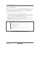
11.3.3 Timer Load Register B1 (TLB1)
TLB1 is an 8-bit write-only register for setting the reload value of TCB1. When a reload value is
set in TLB1, the same value is loaded into TCB1 as well, and TCB1 starts counting up from that
value. When TCB1 overflows during operation in auto-reload mode, the TLB1 value is loaded
into TCB1. Accordingly, overflow periods can be set within the range of 1 to 256 input clocks.
TLB1 is allocated to the same address as TCB1. TLB1 is initialized to H'00.
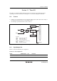
11.4 Operation
11.4.1 Interval Timer Operation
When bit TMB17 in TMB1 is cleared to 0, timer B1 functions as an 8-bit interval timer. Upon
reset, TCB1 is cleared to H'00 and bit TMB17 is cleared to 0, so up-counting and interval timing
resume immediately. The operating clock of timer B1 is selected from seven internal clock signals
output by prescaler S, or an external clock input at pin TMB1. The selection is made by bits
TMB12 to TMB10 in TMB1.
After the count value in TMB1 reaches H'FF, the next clock signal input causes timer B1 to
overflow, setting flag IRRTB1 in IRR2 to 1. If IENTB1 in IENR2 is 1, an interrupt is requested to
the CPU.
At overflow, TCB1 returns to H'00 and starts counting up again. During interval timer operation
(TMB17 = 0), when a value is set in TLB1, the same value is set in TCB1.