
Datasheet


Section 10 Realtime Clock (RTC)
Rev. 3.00 Mar. 15, 2006 Page 153 of 526
REJ09B0060-0300
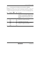
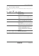
10.3.5 RTC Control Register 1 (RTCCR1)
RTCCR1 controls start/stop and reset of the clock timer. For the definition of time expression, see
figure 10.2.
Bit Bit Name
Initial
Value R/W Description
7 RUN — R/W
RTC Operation Start
0: Stops RTC operation
1: Starts RTC operation
6 12/24 — R/W Operating Mode
0: RTC operates in 12-hour mode. RHRDR counts on 0
to 11.
1: RTC operates in 24-hour mode. RHRDR counts on 0
to 23.
5 PM — R/W a.m./p.m.
0: Indicates a.m. when RTC is in the 12-hour mode.
1: Indicates p.m. when RTC is in the 12-hour mode.
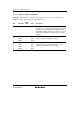
4 RST 0 R/W Reset
0: Normal operation
1: Resets registers and control circuits except RTCCSR
and this bit. Clear this bit to 0 after having been set to
1.
3 INT — R/W Interrupt Generation Timing
0: Generates a second, minute, hour, or day-of-week
periodic interrupt during RTC busy period.
1: Generates a second, minute, hour, or day-of-week
periodic interrupt immediately after completing RTC
busy period.
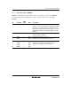
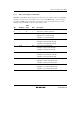
2
1
0
—
—
—
0
0
0
—
—
—
Reserved
These bits are always read as 0.