
Datasheet


Section 9 I/O Ports
Rev. 3.00 Mar. 15, 2006 Page 111 of 526
REJ09B0060-0300
Section 9 I/O Ports
The group of this LSI has fifty-nine general I/O ports and eight general input-only ports. Thirteen
ports are large current ports, which can drive 20 mA (@V
OL
= 1.5 V) when a low level signal is
output. Any of these ports can become an input port immediately after a reset. They can also be
used as I/O pins of the on-chip peripheral modules or external interrupt input pins, and these
functions can be switched depending on the register settings. The registers for selecting these
functions can be divided into two types: those included in I/O ports and those included in each on-
chip peripheral module. General I/O ports are comprised of the port control register for controlling
inputs/outputs and the port data register for storing output data and can select inputs/outputs in bit
units.
For functions in each port, see appendix B.1, I/O Port Block Diagrams. For the execution of bit-
manipulation instructions to the port control register and port data register, see section 2.8.3, Bit
Manipulation Instruction.
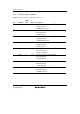
9.1 Port 1
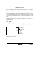
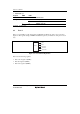
Port 1 is a general I/O port also functioning as IRQ interrupt input pins, an RTC output pin, a 14-
bit PWM output pin, a timer B1 input pin, and a timer V input pin. Figure 9.1 shows its pin
configuration.
P17/IRQ3/TRGV
P16/IRQ2
P15/IRQ1/TMIB1
P14/IRQ0
P12
P11/PWM
P10/TMOW
Port 1
Figure 9.1 Port 1 Pin Configuration
Port 1 has the following registers.
• Port mode register 1 (PMR1)
• Port control register 1 (PCR1)
• Port data register 1 (PDR1)
• Port pull-up control register 1 (PUCR1)