
Datasheet


Section 6 Power-Down Modes
Rev. 3.00 Mar. 15, 2006 Page 79 of 526
REJ09B0060-0300
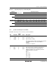
6.1.3 Module Standby Control Register 1 (MSTCR1)
MSTCR1 allows the on-chip peripheral modules to enter a standby state in module units.
Bit Bit Name
Initial
Value R/W Description
7 0 Reserved
This bit is always read as 0.
6 MSTIIC 0 R/W IIC2 Module Standby
IIC2 enters standby mode when this bit is set to 1
5 MSTS3 0 R/W SCI3 Module Standby
SCI3 enters standby mode when this bit is set to 1
4 MSTAD 0 R/W A/D Converter Module Standby
A/D converter enters standby mode when this bit is set
to 1
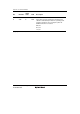
3 MSTWD 0 R/W Watchdog Timer Module Standby
Watchdog timer enters standby mode when this bit is
set to 1.When the internal oscillator is selected for the
watchdog timer clock, the watchdog timer operates
regardless of the setting of this bit
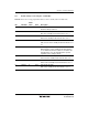
2 MSTTW 0 R/W Timer W Module Standby
Timer W enters standby mode when this bit is set to 1
1 MSTTV 0 R/W Timer V Module Standby
Timer V enters standby mode when this bit is set to 1
0 MSTTA 0 R/W RTC Module Standby
RTC enters standby mode when this bit is set to 1