
Datasheet


Section 6 Power-Down Modes
Rev. 3.00 Mar. 15, 2006 Page 77 of 526
REJ09B0060-0300
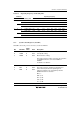
Table 6.1 Operating Frequency and Waiting Time
Bit Name Operating Frequency
STS2 STS1 STS0 Waiting Time 20 MHz 16 MHz 10 MHz 8 MHz 4 MHz 2 MHz 1 MHz 0.5 MHz
0 0 0 8,192 states 0.4 0.5 0.8 1.0 2.0 4.1 8.1 16.4
1 16,384 states 0.8 1.0 1.6 2.0 4.1 8.2 16.4 32.8
1 0 32,768 states 1.6 2.0 3.3 4.1 8.2 16.4 32.8 65.5
1 65,536 states 3.3 4.1 6.6 8.2 16.4 32.8 65.5 131.1
1 0 0 131,072 states 6.6 8.2 13.1 16.4 32.8 65.5 131.1 262.1
1 1,024 states 0.05 0.06 0.10 0.13 0.26 0.51 1.02 2.05
1 0 128 states 0.00 0.00 0.01 0.02 0.03 0.06 0.13 0.26
1 16 states 0.00 0.00 0.00 0.00 0.00 0.01 0.02 0.03
Note: Time unit is ms.
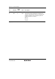
6.1.2 System Control Register 2 (SYSCR2)
SYSCR2 controls the power-down modes, as well as SYSCR1.
Bit Bit Name
Initial
Value R/W Description
7
6
5
SMSEL
LSON
DTON
0
0
0
R/W
R/W
R/W
Sleep Mode Selection
Low Speed on Flag
Direct Transfer on Flag
These bits select the mode to enter after the execution
of a SLEEP instruction, as well as bit SSBY of
SYSCR1.
For details, see table 6.2.
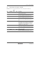
4
3
2
MA2
MA1
MA0
0
0
0
R/W
R/W
R/W
Active Mode Clock Select 2 to 0
These bits select the operating clock frequency in
active and sleep modes. The operating clock
frequency changes to the set frequency after the
SLEEP instruction is executed.
0xx: φ
OSC
100: φ
OSC
/8
101: φ
OSC
/16
110: φ
OSC
/32
111: φ
OSC
/64