
Datasheet


Section 5 Clock Pulse Generators
Rev. 3.00 Mar. 15, 2006 Page 74 of 526
REJ09B0060-0300
5.4 Usage Notes
5.4.1 Notes on Resonators
Resonator characteristics are closely related to board design and should be carefully evaluated by
the user, referring to the examples shown in this section. Resonator circuit constants will differ
depending on the resonator element, stray capacitance in its interconnecting circuit, and other
factors. Suitable constants should be determined in consultation with the resonator element
manufacturer. Design the circuit so that the resonator element never receives voltages exceeding
its maximum rating.
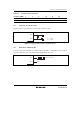
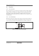
5.4.2 Notes on Board Design
When using a crystal resonator (ceramic resonator), place the resonator and its load capacitors as
close as possible to the OSC
1
and OSC
2
pins. Other signal lines should be routed away from the
resonator circuit to prevent induction from interfering with correct oscillation (see figure 5.11).
OSC
1
OSC
2
C
1
C2
Signal A Signal B
Avoid
Figure 5.11 Example of Incorrect Board Design