
Datasheet


Section 5 Clock Pulse Generators
Rev. 3.00 Mar. 15, 2006 Page 73 of 526
REJ09B0060-0300
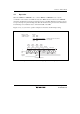
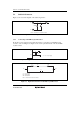
5.2.2 Pin Connection when not Using Subclock
When the subclock is not used, connect pin X
1
to V
CL
or V
SS
and leave pin X
2
open, as shown in
figure 5.10.
X
1
V
CL
or V
SS
X
2
Open
Figure 5.10 Pin Connection when not Using Subclock
5.3 Prescalers
5.3.1 Prescaler S
Prescaler S is a 13-bit counter using the system clock (φ) as its input clock. It is incremented once
per clock period. Prescaler S is initialized to H'0000 by a reset, and starts counting on exit from
the reset state. In standby mode, subactive mode, and subsleep mode, the system clock pulse
generator stops. Prescaler S also stops and is initialized to H'0000. The CPU cannot read or write
prescaler S. The output from prescaler S is shared by the on-chip peripheral modules. The divider
ratio can be set separately for each on-chip peripheral function. In active mode and sleep mode,
the clock input to prescaler S is determined by the division factor designated by the MA2 to MA0
bits in SYSCR2.
5.3.2 Prescaler W
Prescaler W is a 5-bit counter using a 32.768 kHz signal divided by 4 (φ
W
/4) as its input clock. The
divided output is used for clock time base operation of timer A. Prescaler W is initialized to H'00
by a reset, and starts counting on exit from the reset state. Even in standby mode, subactive mode,
or subsleep mode, prescaler W continues functioning so long as clock signals are supplied to pins
X
1
and X
2
.