
Datasheet


Section 5 Clock Pulse Generators
Rev. 3.00 Mar. 15, 2006 Page 72 of 526
REJ09B0060-0300
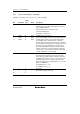
5.2 Subclock Generator
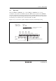
Figure 5.7 shows a block diagram of the subclock generator.
Note: Resistance is a reference value.
2
1
X
8 MΩ
X
Figure 5.7 Block Diagram of Subclock Generator
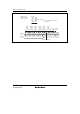
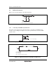
5.2.1 Connecting 32.768-kHz Crystal Resonator
Clock pulses can be supplied to the subclock divider by connecting a 32.768-kHz crystal
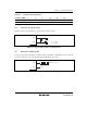
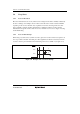
resonator, as shown in figure 5.8. Figure 5.9 shows the equivalent circuit of the 32.768-kHz
crystal resonator.
X
X
C
1
C
2
1
2
C = C = 15 pF (typ.)
12
Figure 5.8 Typical Connection to 32.768-kHz Crystal Resonator
X
1
X
2
L
S
C
S
C
O
C
O
= 1.5 pF (typ.)
R
S
= 14 kΩ (typ.)
fW = 32.768 kHz
R
S
Note: Constants are reference values.
Figure 5.9 Equivalent Circuit of 32.768-kHz Crystal Resonator