
Datasheet


Section 5 Clock Pulse Generators
Rev. 3.00 Mar. 15, 2006 Page 70 of 526
REJ09B0060-0300
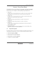
5.1 System Clock Generator
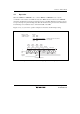
Clock pulses can be supplied to the system clock divider either by connecting a crystal or ceramic
resonator, or by providing external clock input. Figure 5.2 shows a block diagram of the system
clock generator.
LPM
LPM: Low-power mode (standby mode, subactive mode, subsleep mode)
2
1
OSC
OSC
Figure 5.2 Block Diagram of System Clock Generator
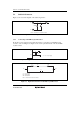
5.1.1 Connecting Crystal Resonator
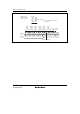
Figure 5.3 shows a typical method of connecting a crystal resonator. An AT-cut parallel-resonance
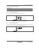
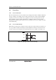
crystal resonator should be used. Figure 5.4 shows the equivalent circuit of a crystal resonator. A
resonator having the characteristics given in table 5.1 should be used.
1
2
C
1
C
2
OSC
OSC
C = C = 10 to 22pF
12
Figure 5.3 Typical Connection to Crystal Resonator
C
S
C
0
R
S
OSC
1
OSC
2
L
S
Figure 5.4 Equivalent Circuit of Crystal Resonator